99
Accessories
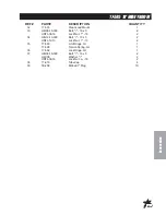
30-162 FOAM MARKER PARTS LIST
REF#
PART#
DESCRIPTION
QUANTITY
1
15-537
Foamer Hose Guard 31"
4
HSDPS-14-075
Stainless Steel Pan Head Drill Screw
1
/
4
x
3
/
4
8
2
16-987
Foam Nozzle Mounting Kit
1 per boom
3
15-507
Foamer Tubing
1
4
Clear Tubing
5
15-511
Foam Nozzle
2
6
Blue Tubing
7
15-510-01
Nozzle Mounting Rod
2
8
Boom
9
16-795
Square Clamp
4
1.
Slide hose clamp onto drop tube of foam nozzle and attach restrictor bell.
2.
Place splined end of Nozzle mounting rod (Ref 7) into top of foam nozzle (Ref 5). Tighten screw.
3.
Slide two foam nozzle mounts (Ref 2) onto the rod. Place square clamps (Ref 9) on foam nozzle mounts and
mount the square clamps to the boom (Ref 8). Adjust foam nozzle mounts and clamps so nozzle assembly will
clear end of boom. Tighten foam nozzle mounts and square clamps to prevent side to side movement. Do the
same to the other side.
4.
Being careful not to cut the tubing (Ref 3), cut the oversleeve back approximately 2" (5 cm) to expose blue (Ref 6)
and clear tubing (Ref 4).
5.
Remove blue wing nut from top connector of foam nozzle and slide it on the blue tube with the threads facing
toward end of tube. Slide blue tube all the way over the top of the small tube on foam nozzle. Slide wing nut back
to the threads and hand tighten. Follow the same steps for the clear tube and tube nut.
6.
Route the tubing along underside of main frame using tie downs as necessary.
7.
Install opposite ends of air-liquid tubes to compressor, again cutting back the oversleeve approximately 2" (5 cm)
and inserting blue and clear tubes for the left boom section into the tubing connectors (Ref A) on the right side of
compressor as far as possible.
8.
Follow the same steps for the right boom tubing. Notice the right boom is inserted into left side of compressor. To
release tubing from compressor, hold black ring around tubing, and pull tube out.
9.
Hose's must be routed on bottom of the boom square tubing.
10.
Mark 6 inches in from inside edge of foamer nozzle mounting bracket on square boom tubing.
11.
Place hose guard (Ref 1) flush with top of square tubing with edge on previous mark. The channel covers hoses
on the bottom of the square tubing.
12.
Install hose guard using 2 drill screws (you may want to drill a
3
/
16
pilot hole first).
13.
Place another hose guard against first and install in same manner.
14.
Repeat process for other boom side.
15.
Connect small plastic electrical plug under compressor to electrical extension cable.
16.
For
Spray Star 1600
route extension cable under engine along the mainframe cross bar, using tie downs as
necessary.
17.
Cut cable and strip casing, allowing enough length to connect to fuse block.
18.
Strip and connect slide on connectors to each wire and use the heat shrink.
19.
Connect black negative (-) wire to the ground and connect red wire to the positive (+).
20.
Insert 10 amp fuse into slot which red wire was attached to.
Summary of Contents for 30-000-C
Page 13: ...11 Service NOTES ...
Page 18: ...16 Parts BODY FRAMEDRAWING ...
Page 20: ...18 Parts NOSECONEDRAWING ...
Page 22: ...20 Parts NOSECONEDRAWING ...
Page 24: ...22 Parts LINKAGEDRAWING ...
Page 26: ...24 Parts FRONTAXLEDRAWING ...
Page 28: ...26 Parts OIL FUELTANKDRAWING ...
Page 30: ...28 Parts SEATPANELDRAWING ...
Page 32: ...30 Parts ENGINEANDPUMPS DRAWING ...
Page 34: ...32 Parts ENGINEANDPUMPS DRAWING ...
Page 36: ...34 Parts COOLERANDEXHAUSTDRAWING ...
Page 38: ...36 Parts REARWHEELDRIVEDRAWING ...
Page 40: ...38 Parts TANKDRAWING ...
Page 42: ...40 Parts TURBO QUADAGITATORDRAWING ...
Page 44: ...42 Parts 15 301ORBITROLDRAWING ...
Page 48: ...46 Parts 30 102EATONPUMPDRAWING ...
Page 50: ...48 Parts 30 102EATONPUMPDRAWING ...
Page 52: ...50 Parts 30 101EATONMOTORDRAWING ...
Page 54: ...52 Parts 30 099 AUBURN POWERWHEEL DRAWING ...
Page 56: ...54 Accessories 3182PLUMBINGDRAWING RAVEN440 15 818 75 Fitting O ring 15 817 50 Fitting O ring ...
Page 58: ...56 Accessories 3184PLUMBINGDRAWING RAVEN203 15 818 75 Fitting O ring 15 817 50 Fitting O ring ...
Page 66: ...64 Accessories CONTROLS3182SYSTEMDRAWING RAVEN 440 ...
Page 68: ...66 Accessories CONTROLS3184SYSTEMDRAWING RAVEN 203 ...
Page 70: ...68 Accessories WIRING 3185 3186 SYSTEM ENVIZIO PRO II SHARP SHOOTER W RATE SYNC ...
Page 72: ...70 Accessories WIRING3187 3188SYSTEM RAVEN440 SHARPSHOOTER ...
Page 76: ...74 Accessories 15 743MANIFOLDVALVEDRAWING ...
Page 78: ...76 Accessories 17 58020 HEAVYBOOM ...
Page 80: ...78 Accessories 17 58020 BOOMDRAWING ...
Page 84: ...82 Accessories 17 585 18 HEAVYBOOM ...
Page 86: ...84 Accessories 17 585 18 HEAVYBOOM ...
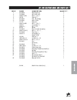
Page 90: ...88 Accessories 30 010ELECTRICHOSEREELDRAWING ...
Page 94: ...92 Accessories HOSEREELMOUNT DRAWING ...
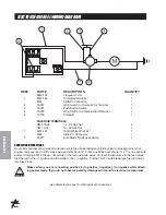
Page 96: ...94 Accessories 30 004FOAMMARKERDRAWING WIRINGDRAWING ...
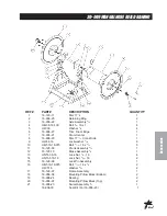
Page 98: ...96 Accessories 30 004FOAMMARKERDRAWING ...
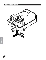
Page 100: ...98 Accessories FOAMER NOZZLEMOUNT HOSEGUARDMOUNTDRAWING ...
Page 103: ...101 Accessories NOTES ...
Page 106: ...104 Accessories 30 006FRESHWATERTANKDRAWING ...
Page 110: ...108 Accessories 15 620CHEMICALCLEANLOAD PARTSDRAWING ...

