background image


No.   

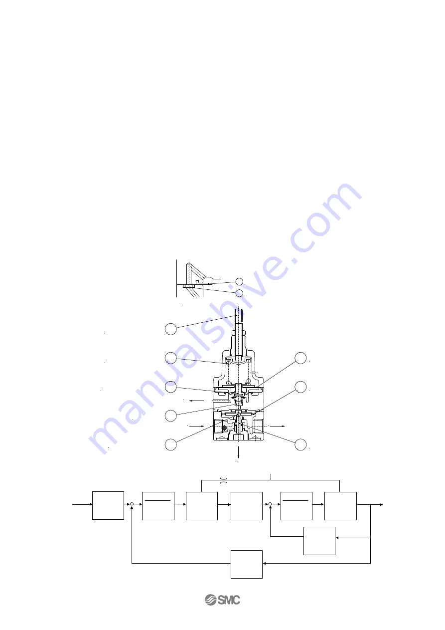
2. Structure and operating principles


  When the Adjusting screw

is turned, the nozzle

  is closed by the diaphragm disk

, allowing the 

supply air that flows in from the upstream side to pass through the fixed orifice

  and to acts on 

diaphragm C

  as nozzle back pressure, the main valve

  is pushed down by the generated force and 

the supply pressure flows out to the downstream side. The air pressure that flows in acts on bottom side 

of diaphragm C

  and while opposing the force generated by nozzle back pressure, it also acts on 

diaphragm A

opposing the compression force of the setting spring

  and balance with set pressure. 

When the output pressure raises above the setting pressure, diaphragm A

  is pushed up which makes 

the interval between the diaphragm disk

  and the nozzle

  widens, the nozzle back pressure drops, 

the pressure balance of upper/bottom part of diaphragms C

  collapses. Then as the main valve


closes, the exhaust valve

  opens at the same time and the excess pressure from the downstream side 

is discharged to the atmosphere. In this way fine pressure variations are detected by the nozzle/flapper 

type pilot mechanism, and precise pressure adjustment is performed. Deviation due to pressure 

difference between in/outside of bourdon tube is transmitted to the sector through the rod to rotate the 

pinion engaging the sector. The indicting needle and scale display the pressure value.


-5-


SUP

OUT

BLEED

E

X

H

5

6

7

9

3

2

8

1

Diaphragm A

Diaphragm C

Main valve

Exhaust valve

Nozzle

Diaphragm disk

Adjusting spring

Adjusting screw

4

Fixed orifice

6

Diaphragm C

SUP.side passage


Setting

spring

N/m

Diaph.C

m

2

Daiph.A

m

2

Nozzle

flapper

          MPa/ m

Diaph.B

m

2

spring

Compd

.

1

(B)

m/N

Main valve

        MPa/ m

(S)

Displ

m


      Force


        N

Displ

m

Press

MPa


      Force


        N

Displ

m

Press.

MPa

Force

N

Force

N

SUP

Fixed


orifice

spring

Compd

.

1

(A)

m/N


Summary of Contents for IR1000 Series

Page 1: ...No IR10 OM00006 PRECISION REGURETOR PRODUCT NAME IR1000 F01 DII00467 IR1010 F01 DII00467 MODEL Series...

Page 2: ...e of Contents Safety 2 3 Specifications 4 Operation principle 5 How to order 6 Production lot number symbol 6 Caution on handling 7 8 Troubleshooting 9 Spare parts list 10 Assembling drawing 11 Drawin...

Page 3: ...indicate the level of potential hazard by labeling Caution Warning or Damage To ensure safety be sure to observe ISO4414 Note 1 JIS B 8370 Note 2 and other safety practices DANGER In extreme conditio...

Page 4: ...r repair of pneumatic systems should be performed by trained and experienced operators 3 Do not service machinery equipment or attempt to remove component until safety is confirmed A Inspection and ma...

Page 5: ...2 0 1 4 Setting sensitivity Note2 within 0 2 of full span Repeatability Note2 within 0 5 of full span Note3 Air consumption Less than 5 l min ANR at supply pressure of 10bar Fluid Air Oxygen Ambient...

Page 6: ...drops the pressure balance of upper bottom part of diaphragms C collapses Then as the main valve closes the exhaust valve opens at the same time and the excess pressure from the downstream side is di...

Page 7: ...to product name plate PRECISION REGULATOR IR1000 F01 DII00467 MAX SUP PRESS 10bar OUTPUT PRESS 0 05 2bar MADE IN JAPAN Symbol of year Symbol of month January February March April May June July August...

Page 8: ...use compressed air which includes chemicals synthetic oils containing organic solvents salt or corrosive gases etc as this can cause damage of malfunction 3 If drains is not removed from air filters a...

Page 9: ...ure adjustment Caution Air supply 1 If the supply pressure line contains drainage or dirt etc the fixed throttle can become clogged leading to malfunction and therefore in addition to an air filter SM...

Page 10: ...r is not exhausted from bleed hole Fixed orifice is clogged Replace the component or fixed orifice Adhering dust to the sealing part of the main valve Remove the dust at the seat by replacing by the c...

Page 11: ...22 FRANCE 33 1 64 76 1000 SPAIN 34 945 18 4100 GERMANY 49 6103 4020 SWEDEN 46 8 603 0700 GREECE 30 1 342 6076 SWITZERLAND 41 52 396 3131 HUNGARY 36 1 371 1343 TURKEY 90 212 221 1512 IRELAND 353 1 403...

Reviews: