SMC Networks HRL Series Manual Download Page 15

User’s

equipment

Oscillator

2

2

2

2

1

3

5

5

5

5

4

CH1

CH2

Optical

system

Circulating fluid

return port

Circulating fluid

return port

Circulating fluid

outlet

Circulating fluid

outlet

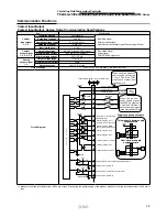
External piping circuit is recommended as shown below.

Parts Description

Recommended External Piping Flow

Cable Specifications

No.

Description

Size

Recommended part no.

Note

1

Filter

Rc1 (5 

μ

m)

Accessory

The value in (  ) shows the nominal filtration accuracy.

2

Valve

Rc1

3

Flow meter

Rc1

Prepare a flow meter with an appropriate flow range.

4

Filter

Rc1/2 (5 

μ

m)

Accessory

The value in (  ) shows the nominal filtration accuracy.

5

Valve

Rc1/2

Power Supply Cable and Earth Leakage Breaker (Recommended)

Model

Power supply voltage 

specifications

Terminal 

block screw 

diameter

Recommended 

crimped

terminal

Cab

le specifications

Earth leakage breaker

Breaker size

[A]

Sensitivity current

[mA]

HRL100-A -20

3-phase 200 VAC (50 Hz)

3-phase 200 to 230 VAC (60 Hz)

M5

R5.5-5

4 cores x 5.5 mm

(4 cores x AWG 10)

including grounding cable

30

30

HRL200-A -20

R8-5

4 cores x 8 mm

(4 cores x AWG 8)

including grounding cable

40

HRL300-A -20

50

   An example of the cable 

specifications

 is when two kinds of vinyl insulated wires with a continuous allowable operating temperature of 70

°

C at 600 V, are 

used at an ambient temperature of 30

°

C. Select the proper size of cable according to an actual condition.
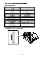
Eye bolt M12

(4 places)

Dustproof 

filter

Dustproof 

filter

Casters and adjuster feet

(4 places of each)

Touch panel

Earth leakage 

breaker handle

Fluid fill po

rt (CH1)

Fluid level

indicator (CH1)

Power cable entry
Signal cable entry

Handle

Handle

Circulating fluid outlet (CH1)

Rc1

Bypass valve (CH1)

Circulating fluid outlet (CH2)

Rc1/2

Bypass valve (CH2)

Fluid fill po

rt (CH2)

Fluid level indicator (CH2)

Tank drain port (CH2)

Rc1/2 (Valve stopper)

Tank drain port (CH1)

Rc3/4 (Valve stopper)

Circulating fluid retu

rn port (CH2)

Rc1/2

Circulating fluid retu

rn port (CH1)

Rc1

14

Circulating Fluid Temperature Controller

Thermo-chiller 

Dual Channel Refrigerated Thermo-chiller for Lasers


HRL

 Series

Summary of Contents for HRL Series

Page 1: ...Cooling capacity kW 9 19 26 CH1 Oscillator 1 Max 1 5 CH2 Optical system Temperature stability C 0 1 0 5 Set temperature range C 15 to 25 20 to 40 1 1 CH2 CH1 CH2 CH1 HRSH200 HRL200 HRS012 Dual thermo...

Page 2: ...with a general refrigerant circuit that controls the compressor by turning the power ON OFF and with a bypass to the circulating uid circuit 1 For HRL300 A 20 mm Space saving Reduced wiring labor Keep...

Page 3: ...emperature difference as high temperature stability can be achieved even with a small size tank This also contributes to space saving One compressor controls 2 channels which realize the independent t...

Page 4: ...screen Set values can be entered from the touch panel Model Cooling method Cooling capacity Power supply Function Accessories CH1 CH2 HRL100 Air cooled refrigeration 9 kW 1 kW Max 1 5 kW 3 phase 200...

Page 5: ...ssigned for specified type of signals Ex 1 Ex 2 Ex 3 Circulating fluid temperature setting Start and stop Circulating fluid discharge temperature Circulating fluid discharge pressure Run and stop stat...

Page 6: ...perating time of a fan Usage time of a DI filter Usage time of a dustproof filter Operation time of a chiller Improved usability and visibility When any alarm is generated the screen automatically mov...

Page 7: ...option Only 200V as an option HRSH Inverter type 0 1 5 to 35 Outdoor installation IPX4 400V as standard 200V as an option Only 200V as an option HRL Inverter dual type CH1 0 1 15 to 25 9 kW 19 kW 26 k...

Page 8: ...F2 200 Pressure Sensor for General Fluids PSE56 Pressure Sensor Controller PSE200 300 300AC Refer to the Web Catalog for details S Coupler KK Series T TU TH TD TL TLM Material Nylon Polyurethane FEP F...

Page 9: ...ommended External Piping Flow p 14 Cable Specifications p 14 Operation Display Panel p 15 Alarm p 15 Communication Functions p 16 Optional Accessories p 19 Cooling Capacity Calculation Required Coolin...

Page 10: ...PBT POM PU PC PVC EPDM NBR CH2 Stainless steel Alumina ceramic Carbon Fluororesin PP PBT POM PU PVC PPS AS PS EPDM NBR Ion replacement resin Electrical system Power supply 3 phase 200 VAC 50 Hz 3 pha...

Page 11: ...id temperature C Cooling capacity kW 35 30 25 20 15 10 5 0 Ambient temperature 32 C Ambient temperature 45 C Cooling capacity kW Circulating fluid temperature C 0 0 0 5 1 0 1 5 2 0 2 5 3 0 20 30 40 Am...

Page 12: ...r for Lasers Anchor bolt mounting position View A Ventilation air outlet Ventilation air inlet Ventilation air inlet A 677 627 330 10 954 1538 40 or less 715 984 1026 HRL100 A 20 Dimensions For piping...

Page 13: ...Thermo chiller for Lasers HRL Series Anchor bolt mounting position View A 715 40 or less 954 330 10 1538 984 1026 677 627 Ventilation air outlet Ventilation air inlet Ventilation air inlet A HRL200 A...

Page 14: ...r Lasers Anchor bolt mounting position View A Ventilation air outlet Ventilation air inlet 850 40 or less 1079 330 10 1839 1109 1145 750 700 A Ventilation air inlet HRL300 A 20 Dimensions For piping p...

Page 15: ...0 VAC 60 Hz M5 R5 5 5 4 cores x 5 5 mm2 4 cores x AWG 10 including grounding cable 30 30 HRL200 A 20 R8 5 4 cores x 8 mm2 4 cores x AWG 8 including grounding cable 40 HRL300 A 20 50 An example of the...

Page 16: ...normal rise of circulating uid temperature AL10 CH1 High Temp CH1 circulating uid temperature rise AL11 CH1 Low Temp CH1 circulating uid temperature drop AL12 CH1 TEMP READY Alarm CH1 TEMP READY alarm...

Page 17: ...make sure that the total load current is 200 mA or less User s system side To the thermo chiller 24 VDC 15 V 100 ANALOG COM 24 COM 1 24 COM 24 VDC Output 4 7 k 4 7 k 4 7 k 15 V 15 V 100 15 V ANALOG C...

Page 18: ...11 Analog output signal 1 Output CH2 circulating fluid temperature 1 12 None Cannot be connected 3 13 None Cannot be connected 3 14 24 COM output Common of contact input signal Output 15 Common of con...

Page 19: ...his product 31st slave SD SD SG 2 SD 7 SD 5 SG This product 1st slave 2 SD 7 SD 5 SG 2 SD 7 SD 5 SG Do not connect with other pins Standards RS 232C Circuit diagram One thermo chiller for one master M...

Page 20: ...ed per unit HRS S0214 Dustproof lter Upper 1 For HRL100 200 A 2 pcs are used per unit HRS S0185 Dustproof lter 1 For HRL300 A 4 pcs are used per unit HRS PF006 Particle lter element 1 Common to each m...

Page 21: ...60 s min 1 Refer to page 21 for the typical physical property value of tap water or other circulating uids Q qm x C x T2 T1 19535 J s 19535 W 19 5 kW Cooling capacity Considering a safety factor of 20...

Page 22: ...pump capacity curves Check beforehand if the circulating uid pipings or circulating uid circuit of the user s equipment are fully durable against this pressure Circulating Fluid Typical Physical Prop...

Page 23: ...uid are not left inside the pipings During operation Air cooled type 2 C to 45 C 5 In locations where condensation may occur 6 In locations which receive direct sunlight or radiated heat 7 In location...

Page 24: ...enough for it to come out the other side 3 Be careful not to bump the fork to the cover panel or piping ports Transportation Carriage Movement Warning 3 Hanging transportation 1 Crane manipulation and...

Page 25: ...it may become impossible to circulate the circulating uid Proceed with caution Mounting Installation Caution 3 Refer to the Operation Manual for this product and secure an installation space that is...

Page 26: ...system Circulation type Make up water Item Unit Standard value In uence Corrosion Scale generation Standard item pH at 25 C 6 0 to 8 0 Electric conductivity 25 C S cm 100 1 to 300 1 Chloride ion Cl m...

Page 27: ...Caution If operating in the conditions below the protection circuit will activate and an operation may not be performed or will stop Power supply voltage is not within the rated voltage range of 10 I...

Page 28: ...r in a place exposed to direct sunlight 2 Installation on equipment in conjunction with atomic energy railways air navigation space shipping vehicles military medical treatment combustion and recreati...

Reviews: