background image


-22- 


No.EX

※※

-OML0011-C 


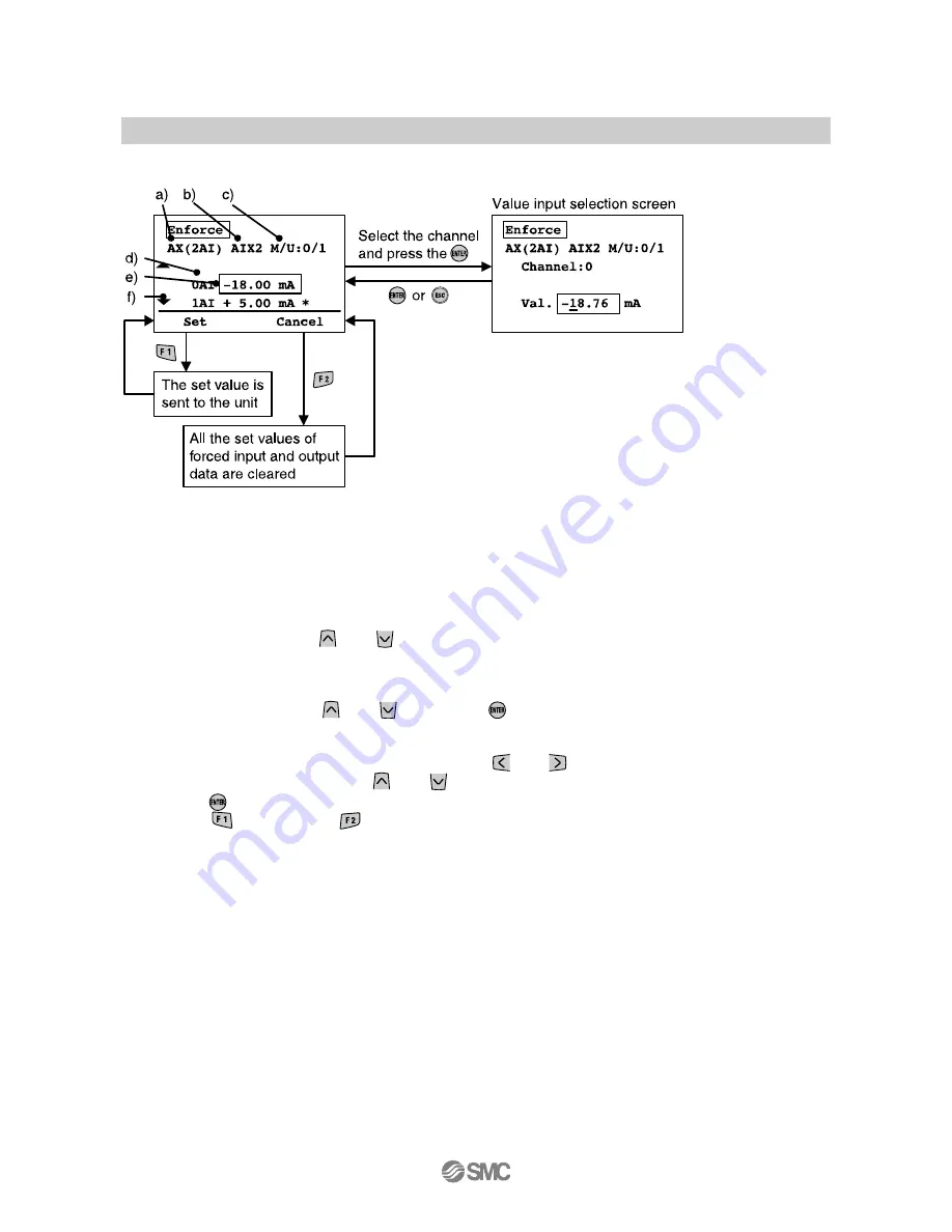
•Forced input and output screen of the Analog unit 


♦Explanation of screen 
a) Displayed unit symbol (Refer to page 

52

b) Tag name (Refer to page 

28)


c) Manifold number/Unit number (Refer to page 

16

d) Channel number 
e) Channel selection cursor 
f) Select the channel with the 

  and 

  buttons. 

g) Display mode switch symbol 
 
 
1. Select the channel with the 

  and 

  buttons and 

  button pressed, the screen shifts to the value 

input selection screen. 

2. An underline is displayed under the digits to be input. 

The underline is shifted to the digits to be set with the 

  and 

  buttons. 

Values and ± are changed with the 

  and 

  buttons. 

3. Press the 

  button to fix the value and return the screen to the previous 53. 

4. Select the 

  button [Set] or 

  button [Cancel]. 

Set: Fix the data selected and send it to the unit. 
Cancel: Reset all the forced input and output data to the current value. 

Summary of Contents for EX600-HT1A

Page 1: ...No EX OML0011 C PRODUCT NAME Fieldbus Device Handheld Terminal MODEL Series Product Number EX600 HT1A ...

Page 2: ...nition and terminology 9 Mounting and Installation 10 Precautions before mounting 10 Wiring 11 Setting and Adjustment 12 Basic operation 12 Mode selection 13 1 I O monitor 15 2 Diagnosis Data 24 3 Sys Configuration 27 4 Parameter Setting 33 5 Terminal Setting 47 Troubleshooting 50 Parameter Setting 52 Specifications 53 Dimensions 53 ...

Page 3: ... equipment failure when configuring the equipment 2 Only personnel with appropriate training should operate machinery and equipment The product specified here may become unsafe if handled incorrectly The assembly operation and maintenance of machines or equipment including our products must be performed by an operator who is appropriately trained and experienced 3 Do not service or attempt to remo...

Page 4: ...r responsibility a replacement product or necessary parts will be provided This limited warranty applies only to our product independently and not to any other damage incurred due to the failure of the product 3 Prior to using SMC products please read and understand the warranty terms and disclaimers noted in the specified catalog for the particular products 2 Vacuum pads are excluded from this 1 ...

Page 5: ... an atmosphere containing flammable or explosive gases Fire or an explosion can result This product is not designed to be explosion proof Do not press the display This may cause injury and damage to the LCD display If using the product in an interlocking circuit Provide a double interlocking system for example a mechanical system Check the product regularly for proper operation Otherwise malfuncti...

Page 6: ...nstallation wiring environment adjustment operation maintenance etc described below must also be followed Product specifications The direct current power supply to combine should be UL 1310 Class2 power supply when conformity to UL is necessary Use the specified voltage Otherwise failure or malfunction can result Do not remove any nameplates or labels This can lead to incorrect maintenance or misr...

Page 7: ...at is exposed to corrosive gases chemicals sea water water or steam Otherwise failure or malfunction can result Do not use in an area where surges are generated If there is equipment generating large surge near the unit magnetic type lifter high frequency inductive furnace welding machine motor etc this can cause deterioration of the internal circuitry element of the unit or result in damage Take ...

Page 8: ...ntenance There is a risk of unexpected malfunction Perform regular maintenance and inspections There is a risk of unexpected malfunction After maintenance is complete perform appropriate functional inspections Stop operation if the equipment does not function properly Otherwise safety is not assured due to an unexpected malfunction or incorrect operation Do not use solvents such as benzene thinner...

Page 9: ...een move the cursor up down left and right to select the item In the setting screen increase decrease or turn ON OFF the set value 4 F2 button Functions according to the display or instructions on the screen 5 Connecter Connects the Cable for Handheld Terminal 6 Cable for Handheld Terminal Connects the SI unit and Handheld Terminal 7 F1 button Functions according to the display or instructions on ...

Page 10: ...he SI unit to adjust the internal parameters monitor the status of all input and output signals and turn on input and output forcedly M Manifold number The number of the EX600 manifold that includes the selected unit This function will be utilized in the future Until then the current state will always be 0 O ON OFF counter Counter of number of times when output or input changes from OFF to ON P Pa...

Page 11: ...00 SPR EX600 SPR A EX600 SDN EX600 SDN A EX600 SMJ EX600 SEN EX600 SEC EX600 SPN Digital input unit EX600 DX B EX600 DX C EX600 DX D EX600 DX E EX600 DX F Disital output unit EX600 DY B EX600 DY E EX600 DY E1 EX600 DY F Digital I O unit EX600 DM E EX600 DM F Analog input unit EX600 AXA Analog output unit EX600 AYA Analog I O unit EX600 AMB 1 EX600 HT1 cannot recognize EX600 D E EX600 D F Ex600 AYA...

Page 12: ...nto the unit vertically If they are not aligned the connector cannot be joined properly 3 When the mark B of the connector has been turned 180 degrees 1 2 turn wiring is completed Confirm that the connection is not loose If turned too far it will become hard to remove the connector 1 2 3 Precautions for handling If there is any foreign matter or water droplets stuck to or inside the SI unit or Han...

Page 13: ...he operation is explained on the following pages Power OFF During Main Menu screen remove the cable connected to the SI unit Power Saving When the button is pressed for 2 seconds or longer while the power supply is ON the display on the display on the LCD screen disappears Press the button to reset it Refer to Terminal Setting page 47 for the details of setting Precautions for handling The connect...

Page 14: ...nit 2 Update the unit structre memorry infomaion 3 Select the Hold Clear function to be set either by the SI unit switches or by the Handheld Terminal 4 Clears the ON OFF counter valve of each unit 5 Resets the parameters of each unit to the default values 6 Clear all error logs 4 Parameter Setting Sets various parameters Refer to page 33 5 Terminal Setting Sets the operation of the Handheld Termi...

Page 15: ...he or button and select the next mode 2 When the mode is selected and the button is pressed the screen shifts to the top screen of each mode 3 To return to the mode selection screen from the top screen of the each mode press the button When each button is pressed the mode shifts in the direction indicated by the arrow ...

Page 16: ...or and channel selection Input and output status of the unit error information and ON OFF count values are displayed Refer to page 17 3 Unit information display The information of the unit selected is displayed Refer to page 19 4 Forced input and output The input and output signal of the unit is forcibly operated with the Handheld Terminal Refer to page 20 Press the button in each screen to return...

Page 17: ...bol Refer to page 52 Select the unit with the and buttons c The next unit structure will be displayed by pressing the or buttons in case of 8 units or more 1 The manifold number is function which will be used for extension in the future so 0 is always display 2 The unit positioned closest to the endplate is numbered as 0 An example is shown below Example of unit number ...

Page 18: ...h Display of channel status OFF ON Error i The next error is displayed with the and buttons j Error code details Refer to page 51 k Counter value SI DX DY DM only The count ON OFF counter values are displayed The update interval of the ON OFF counter value depends on the unit When the power source is turned on counting starts from the counter value that was present at the time the power was switch...

Page 19: ...annels are displayed with the and buttons h Display of channel status When analog data format is set to other than Scaled mA Input or output value Current range V Input or output value Voltage range Error When analog data format is set to Scaled Input or output value Error The or button is pressed the display changes as shown below mA Input or output value Current range V Input or output value Vol...

Page 20: ...it number Refer to page 16 f Number of bytes that SI unit occupies Input Output g Number of total input bytes Digital input Analog input Diagnostic data h Number of total output bytes Digital output Analog output i Number of total digital input bytes j Number of total digital output bytes k Number of total analog input bytes l Number of total analog output bytes m Number of diagnostic information ...

Page 21: ... the output data from PLC Warning The forced input output function is used to change the signal status forcibly When operating this function be sure to check the safety of the surrounding and installation Otherwise injury or equipment damage could result 1 Press the button 2 Enter the password 3 Enforce at the top left starts flashing The display on the forced input and output units will be displa...

Page 22: ...fer to page 16 d Channel number e Channel selection cursor f Select the channel with the and buttons 1 Select the channel with the and buttons 2 Every time the button is pressed the display switches between the three states as shown below 3 Select the button Set or button Cancel Set Fix the data selected and send it to the unit Cancel Reset all the forced input and output to the current value ...

Page 23: ...1 Select the channel with the and buttons and button pressed the screen shifts to the value input selection screen 2 An underline is displayed under the digits to be input The underline is shifted to the digits to be set with the and buttons Values and are changed with the and buttons 3 Press the button to fix the value and return the screen to the previous 53 4 Select the button Set or button Can...

Page 24: ...to enter the password again 1 Press the button 2 Press the button 3 Enter the password Select the digit to be entered with the and buttons Select the characters with the and button Every time the button is pressed the value will change from A to Z and 0 to 9 When the button is pressed the value changes in the opposite direction If the password does not match wrong password is displayed on the inpu...

Page 25: ...information are displayed Refer to page 17 18 2 Display of error details Diagnostic error information is displayed per system and unit in detail Refer to page 25 3 Error log indication The latest error log of the EX600 system is displayed in the order errors were generated 30 errors max Refer to page 26 Press the button in each screen to return to the previous screen 1 Data monitor and channel sel...

Page 26: ... The unit structure is displayed with the and buttons in case of 8 units or more d The next error is displayed with the and buttons in case of multiple errors e Error code Refer to page 51 f Error code details Refer to page 51 When the unit is selected and the button is pressed the screen shift to the channel status display screen Refer to page 24 ...

Page 27: ...o page 16 c Channel number d Displayed unit symbol Refer to page 52 e The next error log is displayed with the and buttons f h hour m minute s second The time elapsed from when the power supply was applied until the time when error was generated is displayed When the power supply of the SI unit is turned off the time is reset g Error code Refer to page 51 h Error code details Refer to page 51 ...

Page 28: ... compiled Refer to page 28 2 Re Register The structure memory information of the unit is updated Refer to page 29 3 Hold Clear This mode is used to select whether the Hold Clear function is set by the switch on the SI unit or by the Handheld Terminal Refer to page 30 4 Clr Counter Value The ON OFF counter value of each unit is cleared Refer to page 31 5 Parameter Default Parameters of each unit ar...

Page 29: ...y name for each unit 1 Select 1 Tag Input and press the button 2 Select the unit with the and buttons and press the button 3 Edit the tag name Refer to Password input page 23 for how to edit the tag name 4 Press the button The compilation of the tag name is completed ...

Page 30: ...h the current unit structure in EX600 If the structure is different a diagnostic error will be generated 1 Select 2 Re Register and press the button 2 Press the button 3 Press the button The update of the structure memory is completed 1 PROFIBUS DP compatible SI unit is not applicable to memory structure ...

Page 31: ...y Carry out settings paying attention to safety Otherwise injury or equipment damage could result 1 Select 3 Hold Clear and press the button 2 Press the or buttons to select Handheld or Switch Handheld Hold Clear function is carried out using the Handheld Terminal setting Switch Hold Clear function is carried out using the switch setting of the SI unit 3 Press the button This selects the mode and ...

Page 32: ...nit 4 Press the button 3 The counter value of each channel of the unit selected is displayed Select the channel with the and buttons If all the channels are cleared this operation is not necessary 1 Select 4 Clr Counter Value and press the button 5 Press the button The counter values of the channel selected or all of the channels are cleared ...

Page 33: ... and return to the system operation setting screen Warning Incorrect setting of parameters can cause malfunction Be sure to check the settings before use Otherwise injury or equipment damage could result 6 Clear Error Log 1 Select 6 Clear Error Log and press the button 2 Press the button Clears all the error logs and returns to the system operation setting screen ...

Page 34: ... the parameters of the unit selected are displayed Refer to page 34 2 Explanation of parameter Parameter details are explained Refer to page 34 3 Unit parameter setting Parameters of each unit are set Refer to page 35 4 Channel parameter setting Parameters of each channel are set Refer to page 41 Press the button in each screen to return to the previous screen ...

Page 35: ...ach parameter to be set b The next parameter is displayed with the and buttons c Parameters that can be set in each unit only d Parameters that can be set in each channel only 2 Explanation of parameter Explanation of screen a Name of each parameter to be set b Parameter details ...

Page 36: ...een returns to the unit parameter selection screen 1 Press the button on the parameter selection screen Or select the parameters where the unit in the object is selected and press the button 2 Enter the password 3 Select the parameter with the and buttons and press the button Refer to Unit parameter setting for the details of setting page 36 to 40 4 Select the setting value with the and buttons an...

Page 37: ...r Symbol Unit parameter selection screen 1 Analog data format D_Format Select with the and buttons 2 Under range detection Undr_Rng Select with the and buttons Information on the parameters can be found in the manual for the SI unit ...

Page 38: ... range detection Over_Rng Select with the and buttons 4 The power supply short circuit detection for the input or output device SC_MonOp SC_MonSs Op Output Ss Sensor power supply Select with the and buttons Information on the parameters can be found in the manual for the SI unit ...

Page 39: ...election screen 5 Restart after output load short circuit SC_RstOp Select with the and buttons 6 Power supply for control and input voltage monitor PWRC_Mon Select with the and buttons Information on the parameters can be found in the manual for the SI unit ...

Page 40: ...Unit parameter selection screen 7 Power supply for output voltage monitor PWRO_Mon Select with the and buttons 8 Inrush current filter Inrush Select with the and buttons Information on the parameters can be found in the manual for the SI unit ...

Page 41: ... Symbol Unit parameter selection screen 9 Input filtering time Filter_T Select with the and buttons 10 Input extension time SigExt_T Select with the and buttons Information on the parameters can be found in the manual for the SI unit ...

Page 42: ...Select the setting value with the and buttons and press button 6 Press the button to complete the setting To copy the set value to channels of the same type in the unit press the button 1 Press the on the parameter selection screen Or select the parameters where the channel in the object is selected and press the button 2 Select the channel and press the button When the button is pressed the infor...

Page 43: ...meter Symbol Channel parameter selection screen 1 Analog average filter Filter Select with the and buttons 2 Analog range Range Select with the and buttons Information on the parameters can be found in the manual for the SI unit ...

Page 44: ...d buttons Move the digit to input with the and buttons Changes the values with the and buttons 4 User setting value lower limit error Lwr_Lmt Select with the and buttons Move the digit to input with the and buttons Changes the values with the and buttons Information on the parameters can be found in the manual for the SI unit ...

Page 45: ... with the and buttons Move the digit to input with the and buttons Changes the values with the and buttons 6 Scale lower limit setting LwLm Scl Select with the and buttons Move the digit to input with the and buttons Changes the values with the and buttons Information on the parameters can be found in the manual for the SI unit ...

Page 46: ...cale upper limit setting UpLm Scl Select with the and buttons Move the digit to input with the and buttons Changes the values with the and buttons 8 Open circuit detection OC_Mon Select with the and buttons Information on the parameters can be found in the manual for the SI unit ...

Page 47: ...ng communication fault Fault_MD Fault_MA MD Digital output MA Analog output Select with the and buttons 10 Output setting for communication idling Idle_MD Idle_MA MD Digital output MA Analog output Select with the and buttons Information on the parameters can be found in the manual for the SI unit ...

Page 48: ...o the mode selection screen Mode Outline Default setting Contrast The contrast the LCD display is set in 9 stages 0 to 8 4 Bright The brightness of the LCD display is set in 5 stages 0 to 4 2 Key Sound The button click sound volume is set in 5 stages 0 to 4 2 PowerSave The time until the unit goes into POWER SAVE mode when no button operation is performed is set 5 stages OFF 1 min 3 min 7 min and ...

Page 49: ...pressed the value changes from A to Z and 0 to 9 When the button is pressed the value changes in the opposite direction If the password does not match wrong password is displayed on the input screen In that case enter the correct password again 3 Enter a new password The method of entering the password is the same as above 4 Press the button A new password is set and the screen is returned to the ...

Page 50: ...w password can then be set 1 Enter PASS and press the button is displayed on the lower right of the screen 2 Enter WORD and press the button 3 Enter a new password The setting method is the same as in password change mode 4 Press the button A new password is set and the screen is returned to the terminal setting screen ...

Page 51: ... the LCD display turns ON LCD failure Stop using the product Contact your sales representative 4 Warning System access is not completed is displayed Connection failure of the cable for Handheld Terminal Check the cable for Handheld Terminal EX600 units are not connected properly If the ST M LED of the SI unit is flashing in red and green alternately check whether the units are connected properly 5...

Page 52: ...et by user has exceeded the upper limit 8 Analog value value set by user has exceeded the lower limit 9 ON OFF count has exceeded the set value 10 to 15 16 Power supply voltage level for control and inputs is abnormal 17 Power supply voltage level for output is abnormal 18 19 Connection error between the units When operating 20 Connection error between the units When power is supplied 21 Configura...

Page 53: ...Y 24DO EX600 DY E1 Digital I O DM DM 8DI8DO EX600 DM E EX600 DM F Analog input AX AX 2AI EX600 AXA Analog output AY AY 2AO EX600 AYA Analog I O AM AM 2AI2AO EX600 AMB SI unit Occupies 8 outputs SI SI 8SOL EX600 SDN EX600 SDN A EX600 SPR EX600 SPR A EX600 SMJ EX600 SEN EX600 SEC EX600 SPN SI unit Occupies 16 outputs SI 16SOL EX600 SDN A EX600 SPR A EX600 SMJ EX600 SEN EX600 SEC EX600 SPN SI unit Oc...

Page 54: ...ent consumption 50 mA or more Display LCD with back light Resolution 128x64 dot Connector Handheld Terminal 14 pin connector Connector SI unit M12 connector Environment Enclosure IP20 Operating temperature range 10 to 50 oC Storage temperature range 20 to 60 oC Operating humidity range 35 to 85 RH No condensation Standard CE marking RoHS Weight 160 g Dimensions ...

Page 55: ...nction B Limited warranty and Disclaimer are added C Contents revised in several places March 2017 Note Specifications are subject to change without prior notice and any obligation on the part of the manufacturer 2010 2017 SMC Corporation All Rights Reserved ...

Reviews: