


10
11
Wiring ( continued )
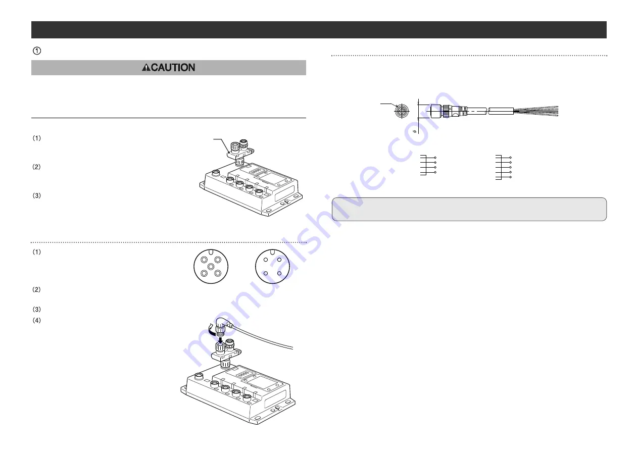
Communication wiring
Align with key groove, plug the
bus adapter into the communication
connector.
Tighten the lock nut by turning it
clockwise by hand, and confirm that the
connector does not move.
Connect the cables with CC-Link communication
connectors to the mating CC-Link communication
connectors ( bus adapter ) as shown below.
Cable connection
Align the key groove with the IN
connector ( plug ) of the bus adapter of
GW unit, fit on the CC-Link communication
cable ( socket ).
Tighten the lock nut on cable side by
turning it clockwise by hand.
Confirm that the connector portion does not move.
Similar to the above, connect the other
communication cable ( plug ) to the
OUT connector of the bus adapter.
If this EX500 is the terminal of CC-Link
connection, connect the terminal resistor.
Refer to "Connection of terminal resistor"
( page 12 ) in this manual.
Avoid the mixing of CC-Link dedicated high-performance cable and other cables
( CC-Link dedicated cable and/or Version 1.10 compatible CC-Link dedicated
cable ).
The mixing can hinder the normal data transmission and cause a problem.
Pin layout and connection diagram of cable with CC-Link communication connectors
Connect the communication cable with socket-type M12 connector on IN side and plug-
type M12 connector on OUT side.
For cable to be used, refer to "Appendix Table" ( page 41 ) in this manual.
IN side
SLD
DB
DG
DA
1
2
3
4
Shield
White
Yellow
Blue
Connection Diagram
OUT side
Connection Diagram
SLD
DB
DG
DA
NC
1
2
3
4
5
Shield
White
Yellow
Blue
NC
M12
14.9
NOTE
Connect the shield wire of CC-Link dedicated cable to "SLD" of each unit.
1
2
4
3
OUT
2
1
3
4
IN
5
Bus adapter


