


29
-
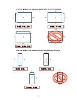
“2
×
2
-‐
1”
will show channels 1 ~ 4 split into 4 screens and
“2
×
2
-‐
2”
will
show channels 5 ~ 8 split into 4 screens.
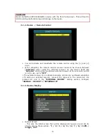
Ø
EMS Alert Unit
- USE: Select
“ON”
using the [>] and [<] keys.
-‐
ACC/DEC VALUE: The G-sensor Warning Light on the EMS Alarm Display Unit
will illuminate when the G-sensor senses momentum exceeding the set level.
Levels can be adjusted from 0.1G to 1.0G.
- SPEED VALUE: The Speed Warning Light on the EMS Alarm Display Unit will
illuminate when the speed exceeds the set level. The level can be adjusted
from 000 to 999 using the arrow keys.
-‐
RPM VALUE: The RPM Warning Light on the EMS Alarm Display Unit will
illuminate when the RPM exceeds the set level. The level can be adjusted
from 0000 to 9999 using the arrow keys.
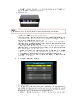
- IDLING TIME (MIN): The Idling Warning Light on the EMS Alarm Display
Unit will illuminate when the driver idles for more than the set time. The time
is in minutes and can be adjusted from 000 to 999 using the arrow keys.
- BUZZER: When set to “ON”, a buzzer will sound in addition to the
illumination for all alarms.
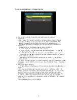
3-1-6. DEVICE/
EXTERNAL DEVICE
Ø
Serial Port Usage
* The SVC series has three serial ports: [S1/S2/S3]. S1 (Serial Port 1) is
used solely for debugging and maintenance while S2 (Serial Port 2) and S3
(Serial Port 3) may be used to connect various external devices such as GPS,
External IR receiver, Tachometers and the EMS Alert unit.
- SERIAL2 – DEVICE and SERIAL3 – DEVICE: Use the arrow keys to select
Note
The EMS Alert Unit is an optional accessory and can be purchased separately.
Summary of Contents for SVC400GPS-L
Page 43: ...43 3 1 1 PC Viewer Control Buttons ...
Page 44: ...44 3 1 2 Control Buttons and Indicators ...
Page 57: ...57 Blurred Image ...
Page 86: ...86 Appendix C Recording Time Table ...
Page 87: ...87 ...
Page 88: ...88 ...


