background image

8  Power Control

SMA Solar Technology AG

66

SCCP-JP-BA-A4-en-12

User Manual

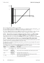
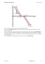
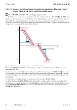
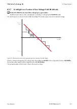
Figure 27: Limitation of the parameter 

Pmax

 to the parameter 

QoDQmax

If the value of 

Pmax

 exceeds the value of 

QoDQmax

, the characteristic curve will be limited to QoDQmax at the value 

Q

QoDmax

 and the reactive power value will remain constant at QoDQmax in the range from +QQoDmax to +Pmax.

If the value of ‒

Pmax

 falls below the value of ‒

QoDQmax

, the characteristic curve will be limited to ‒QoDQmax at 

the value ‒Q

QoDmax

 and the reactive power value will remain constant at ‒QoDQmax in the range from ‒Pmax to 

‒QQoDmax.

Summary of Contents for Sunny Central 500CP-JP

Page 1: ...SCCP JP BA A4 en 12 98 103200 02 Version 1 2 ENGLISH User Manual SUNNY CENTRAL 500CP JP 630CP JP 800CP JP...

Page 2: ...cognized even if not explicitly identified as such A lack of identification does not mean that a product or symbol is not trademarked The Bluetooth word mark and logos are registered trademarks owned...

Page 3: ...onitoring in Grounded PV Arrays 22 3 7 2 1 Ground Fault Detection and Interruption GFDI 22 3 7 2 2 Remote GFDI 23 3 7 2 3 Soft Grounding 24 3 7 3 Insulation Monitoring 25 3 7 3 1 Insulation Monitoring...

Page 4: ...ance 44 6 5 Configuring the Remote Shutdown 44 6 6 Deactivating the Fully Hermetic Transformer Protection 44 7 Grid Monitoring 45 7 1 How Grid Monitoring Works 45 7 2 Setting Line Voltage Monitoring 4...

Page 5: ...int 63 8 3 Q at Night 63 8 3 1 Selecting Parameter QoDQ VarMod 63 8 3 2 No Q at Night Off Mode 65 8 3 3 Q at Night with Setpoint Command via Modbus Protocol VArCtlCom Mode 65 8 3 4 Q at Night with Abs...

Page 6: ...umber 34xx to 40xx Disturbance on PV Array 79 10 4 5 Error Numbers 60xx to 90xx Disturbance on the Sunny Central 81 11 Instantaneous Values 85 11 1 Sunny Central 85 11 1 1 Power Limitation 85 11 1 2 E...

Page 7: ...ion for SUNNY CENTRAL 500CP JP 630CP JP 800CP JP Technical Information Important Requirements for Medium Voltage Transformers and Transformers for Auxiliary Power Supply for SUNNY CENTRAL Inverters of...

Page 8: ...m Detect Button Key Button or key to be selected or pressed Select Start detection Complete designation Designation in this document Sunny Central Inverter Sunny Central Communication Controller SC CO...

Page 9: ...further information in the Technical Information Medium Voltage Transformer Important Requirements for Medium Voltage Transformers and Transformers for Auxiliary Power Supply for SUNNY CENTRAL Invert...

Page 10: ...Internal power supply DC voltage from the PV array Additional external voltages e g control signals from a control room Ensure that no disconnected components can be reconnected After disconnecting t...

Page 11: ...erters located opposite each other blocks the escape route It is imperative that the escape route is freely accessible at all times An escape route with a passage width of at least 500 mm must be avai...

Page 12: ...When working on the Sunny Central and handling assemblies observe all ESD safety regulations Wear suitable personal protective equipment for all work on the device Discharge electrostatic charge by t...

Page 13: ...proof soles and steel toe caps During precipitation or on moist ground safety boots of category S5 with perforation proof soles and steel toe caps Tight fitting work clothes made of 100 cotton Suitabl...

Page 14: ...ral The Sunny Central is controlled via the Sunny Central Communication Controller SC COM The grid management service specifications from the grid operator can be implemented via a Power Reducer Box o...

Page 15: ...rom the touch display Reading off the firmware version You can read off the version number of the Sunny Central and touch display firmware via the user interface You can also read off the version numb...

Page 16: ...3 Operating Modes The Sunny Central cycles through various states during operation Figure 3 Principle overview of the operating states of the Sunny Central in normal operation Observe the documentatio...

Page 17: ...lay If the input voltage VPV is higher than the start voltage PvVtgStrLevMin the Sunny Central waits until the time specified in the parameter PvStrT has elapsed If the input voltage VPV does not fall...

Page 18: ...state Stop If the key switch is turned to Stop while the Sunny Central is in the operating state MPP load operation the Sunny Central switches to the operating state Shutdown Once the shutdown is comp...

Page 19: ...diagnosis Control network This network is used by the Power Reducer Box or Power Plant Controller to transmit grid management specifications issued by the grid operator to the Sunny Central The use o...

Page 20: ...the remote shutdown is similar to the stop function of the key switch If the remote shutdown function is activated from the control room while the Sunny Central is in the operating state Grid monitor...

Page 21: ...When the switch is closed the all or nothing relay is activated and the Sunny Central feeds into the grid If the fast stop is tripped the switch opens and the relay is deactivated The Sunny Central is...

Page 22: ...sonal hazard due to leakage currents or system failure If the insulation resistance falls below the configured warning threshold the system may be switched off Use the parameter IsoErrIgn to activate...

Page 23: ...ny Central and connected between an input busbar and the grounding busbar Figure 7 Remote GFDI in the Sunny Central If the Remote GFDI triggers initially a temporary error will be assumed and a motor...

Page 24: ...idual current will occur through the Soft Grounding resistor The residual current increases the voltage of the grounded terminal against ground potential This enables monitoring of insulation with Sof...

Page 25: ...sulation monitoring device activates the relay with changeover contact This relay is integrated in the Sunny Central If the insulation resistance falls below the error threshold 1 k an insulation erro...

Page 26: ...tes one of the errors 3501 Insulation error 3504 Insulation error ignored or 3601 Warning insulation error is displayed the insulation is defective In this case a qualified person will need to check a...

Page 27: ...h back to feed in operation after a defined delay In the default setting the Sunny Central software will attempt to start the Remote Soft Grounding up to three times per day If the Remote Soft Groundi...

Page 28: ...rters quickly and reliably for implementation The following figure shows how the specifications of the grid operator are implemented The Power Reducer Box or Power Plant Controller sends the specifica...

Page 29: ...eive any updated default values it will utilize the specified proxy values for active power limitation reactive power setpoint and displacement power factor In this case different proxy values can be...

Page 30: ...al after a signal from the grid operator or the safety system for the grid transfer point Ratio VGrid V Behavior of the Sunny Central 90 to 100 The ratio of line voltage VGrid to nominal voltage V is...

Page 31: ...n Q at Night operation for one hour or the DC current falls below 60 A the DC switchgear opens The inverter continues to feed in reactive power If reactive power feed in is interrupted after a grid fa...

Page 32: ...of stand alone grids and disconnects the Sunny Central from the utility grid Islanding can occur when at the time of utility grid failure the load in the shut down sub grid is roughly equivalent to t...

Page 33: ...stantaneous values and parameter settings The functions are activated by tapping on the appropriate symbols on the touch display The touch display is divided into three areas Figure 13 Touch display a...

Page 34: ...he type of string current monitoring DC currents of the individual Sunny String Monitors This symbol appears once you have selected the symbol Switch on DC or AC side closed If you see this symbol bet...

Page 35: ...pe of the displacement power factor Actual reactive power in VAr Actual displacement power factor cos Actual excitation type of the displacement power factor Symbol Designation Explanation Language se...

Page 36: ...his symbol to see the following information OS version of the operating system App version of the application software Language selected language Ser No Serial number of the Sunny Central Error This s...

Page 37: ...hour format 5 Select the number format 6 Confirm your entry by selecting 4 6 Setting the Brightness 1 Select 2 Select 3 Set the display brightness Select for a darker screen or for a lighter screen 4...

Page 38: ...rated in the same network the SC COM of each Sunny Central must be assigned a unique network address Figure 15 Example of a plant network with two Sunny Central inverters Procedure Setting the IP addr...

Page 39: ...1 Subnet mask 255 0 0 0 8 In the Local Area Connection Properties window select OK The settings are now applied 9 Select OK in the Network Connections window This closes the window The computer is now...

Page 40: ...ter the installer password in the appropriate field on the homepage and confirm with Login 3 Select PV system Devices 4 Select A list of the existing device types appears 5 Select the desired device t...

Page 41: ...ting Sunny String Monitors via the Sunny Central String Monitor Controller Procedure 1 Select the Parameters tab 2 Set the parameter DevFunc to AutoDetect_SSMU 3 Confirm the entry with Save 4 Select t...

Page 42: ...10 00 a m to 3 00 p m by default Procedure 1 Select the parameter MoniTmComOn and set the start of the communication period see Section 6 2 page 40 2 Select the parameter MoniTmComOff and set the end...

Page 43: ...entral String Monitor Controller the PV string data is continuously monitored and the group data compared so that potential errors are detected immediately It is therefore advisable to split the PV st...

Page 44: ...switched with 24 V see Sunny Central installation manual To use this function the associated parameter must be activated Procedure 1 Ensure that the Sunny Central is in the operating state Stop 2 Log...

Page 45: ...ing before the Sunny Central disconnects from the utility grid 7 2 Setting Line Voltage Monitoring You can specify the thresholds and tripping time manually For voltage monitoring you can set two limi...

Page 46: ...level 2 is breached timer for A starts counting 6 Grid limit level 2 is breached for delay time level 2 grid disconnection 7 Grid limit level 1 is breached for delay time level 1 grid disconnection h...

Page 47: ...e Sunny Central it will only switch back on once the line voltage has met certain conditions The line voltage and the power frequency must remain within the set thresholds for grid connection for the...

Page 48: ...nny Central has switched off due to grid limit infringement you can prevent an automatic restart of the Sunny Central The Sunny Central will not switch back on until the error has been acknowledged Yo...

Page 49: ...r indicates the percentage of the saved power Pcur by which the power per Hz will be reduced if the power frequency continues to rise If the power frequency decreases again as shown in point B the las...

Page 50: ...2 page 40 4 Change any parameters associated with the selected mode Example A 500 kW Sunny Central is feeding 350 kW Pcur into the utility grid The frequency rises to 51 2 Hz The difference between t...

Page 51: ...If the Sunny Central has not received any signal for five minutes the error message will be displayed in the instantaneous value P WModFailStt 8 1 2 4 Active Power Limitation with Absolute Value WCns...

Page 52: ...face see Section 6 1 page 40 8 1 4 Displaying Error Messages and Warnings for Active Power Limitation The instantaneous value P WModFailStt displays errors or warnings associated with active power lim...

Page 53: ...cabling between the Sunny Central and Power Reducer Box or the Power Plant Controller is OK AnInFail The WCnstNomAnIn mode has been selected and the value measured at the analog input is less than 2...

Page 54: ...helps perform voltage stabilizing measures in the event of overvoltage or undervoltage The parameterization is carried out by means of a reactive power voltage characteristic curve VArCtlVolHysDbA The...

Page 55: ...VArNom refers to Pmax If the calculated amount of reactive power exceeds the predefined value of Qmax the power will be limited to Qmax If the calculated amount of reactive power falls below the prede...

Page 56: ...itation 8 2 1 9 Displacement Power Factor cos via Standard Signal PFCnstAnIn Mode The reactive power setpoint is set via an analog signal at the input terminals for setpoint specification see Sunny Ce...

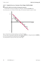
Page 57: ...e can be configured as rising or falling The start and end points of the characteristic curve can be set via parameters Figure 20 Characteristic curve for reducing reactive power as a function of acti...

Page 58: ...ic curve for reducing reactive power as a function of the line voltage If the line voltage is changed by the configurable voltage difference Q VDif for the configurable duration of Q VDifTm the reacti...

Page 59: ...age or undervoltage The parameterization is carried out by means of a reactive power voltage characteristic curve The characteristic curve can be flexibly configured by parameterizing the slope a type...

Page 60: ...trol SMA Solar Technology AG 60 SCCP JP BA A4 en 12 User Manual Figure 23 Characteristic curve for reducing reactive power with deadband Figure 24 Characteristic curve for reducing reactive power with...

Page 61: ...t is actively used In order to prevent several systems with this function from interfering with each other the parameter Q VArTmsVtg can be used to set a delay time This delay time defines how long a...

Page 62: ...r setpoint is actively used In order to prevent mutual interference of several systems with this function the parameter Q VArTmsVtg can be used to set a delay time This delay time defines how long a v...

Page 63: ...er Box or Power Plant Controller can be accessed via the Internet Ensure that the Sunny Central and the Power Reducer Box or the Power Plant Controller are connected correctly Ensure that the cabling...

Page 64: ...power setpoint is imported via an analog input The analog value is converted into a reactive power setpoint VArCtlVol The reactive power is set as a function of the line voltage VArCtlVolHystDb The pr...

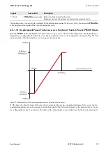
Page 65: ...e of QoDQmax the power will be limited to QoDQmax 8 3 6 Q at Night via Standard Signal VArCnstNomAnIn Mode The reactive power setpoint is set via an analog signal at the input terminals for setpoint s...

Page 66: ...x the characteristic curve will be limited to QoDQmax at the value QQoDmax and the reactive power value will remain constant at QoDQmax in the range from QQoDmax to Pmax If the value of Pmax falls bel...

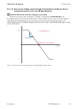
Page 67: ...curve for reducing reactive power as a function of the line voltage If the line voltage is changed by the configurable voltage difference Q VDif for the configurable duration of Q VDifTm the reactive...

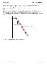
Page 68: ...of overvoltage or undervoltage The parameterization is carried out by means of a reactive power voltage characteristic curve The characteristic curve can be flexibly configured by parameterizing the s...

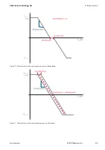
Page 69: ...echnology AG 8 Power Control User Manual SCCP JP BA A4 en 12 69 Figure 30 Characteristic curve for reducing reactive power with deadband Figure 31 Characteristic curve for reducing reactive power with...

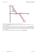
Page 70: ...t is actively used In order to prevent several systems with this function from interfering with each other the parameter Q VArTmsVtg can be used to set a delay time This delay time defines how long a...

Page 71: ...setpoint is actively used In order to prevent mutual interference of several systems with this function the parameter Q VArTmsVtg can be used to set a delay time This delay time defines how long a vo...

Page 72: ...p 2 Wait 15 minutes before opening the Sunny Central This will ensure that the capacitors are discharged 3 Open the Sunny Central 4 Manually switch the GFDI circuit breaker off 5 Close the Sunny Centr...

Page 73: ...device checks each terminal of the PV array for potential insulation errors Switching to insulated operation is useful for performing maintenance or service work on or near the PV array e g cutting th...

Page 74: ...r performing maintenance or service work on or near the PV array e g cutting the grass or for checking the status of the insulation at regular intervals 9 3 2 Switching to Insulated Operation 1 Set th...

Page 75: ...value view 5 To display the corrective measure select the instantaneous value Dsc in the instantaneous value view 10 3 Acknowledging Disturbance Messages Once the error has been remedied you can ackn...

Page 76: ...isturbance is no longer shown on the touch display The Sunny Central then checks whether the cause of the error has been rectified If the cause of the disturbance still exists after the waiting time h...

Page 77: ...it is deleted from the fault memory To view previous disturbances after they have been deleted from the fault memory an event report is filed on the SD memory card The event report logs the time and...

Page 78: ...ervoltage detected by redundant monitoring 30 s 30 s Check line voltage Check grid connections Check stability of the utility grid Make sure the external fuses function properly Make sure the AC cable...

Page 79: ...ge may have to be acknowledged manually Error no Explanation Behavior of the Sunny Central Corrective measures S 1 S 2 R 3403 Voltage of PV array is too high 15 min 30 min Check DC input voltage Check...

Page 80: ...oCtlWarn has been reached W W Check grounding and equipotential bonding Check module wiring and PV system design Check the RisoCtlWarn parameter 3803 Current of PV array is too high 1 min D x Check DC...

Page 81: ...and digital signal processor invalid 5 min 5 min x 6120 Watchdog tripping error 30 s W 6121 No response from watchdog 30 s W 6122 Ten internal monitoring errors have occurred in succession W 5 min 61...

Page 82: ...7 Capacitor self test failed Q Q 6461 Insulation monitoring device has not adopted threshold 15 min 15 min x Ensure that insulation monitoring device and wiring OK 6501 Internal temperature in Sunny C...

Page 83: ...l Contact the SMA Service Line 7706 AC circuit breaker has tripped 30 s Q Contact the SMA Service Line 7707 Faulty switching state of AC contactor 30 s Q 7708 Faulty switching state of Remote GFDI W W...

Page 84: ...e been opened during operation 30 s 1 min x 9009 Fast stop has been manually tripped 30 s 30 s Eliminate error and switch fast stop back on 9013 This is a grid stability shutdown see Section 3 8 7 The...

Page 85: ...tpoint information Name Display Description P WModStt Off No mode for active power limitation has been selected WMax Active power is limited by specification of an upper limit This limit is relative t...

Page 86: ...ErrNo Error number ErrNoFirst Error number of the first error Error Localization of error GriSwStt State of AC contactor Mode Operating state of inverter Msg Error message Prio Priority of error mess...

Page 87: ...f interior fan 1 in h CntFanCab2 Operating hours of interior fan 2 in h CntFanHs These instantaneous values are only visible after entering the installer password Operating hours of heat sink fan in h...

Page 88: ...ware 6 CRC SvmMode Name Description MeanCurGr1 Mean current for group 1 mean value exists for all 6 groups SSMUWrnCode String failure detection SSMUNoOf Number of Sunny String Monitors found Name Desc...

Page 89: ...value of string 1 over the last 30 seconds mean value exists for all eight measuring channels Name Description Alarm contact 1 Status of alarm contact 1 Alarm contact 2 Status of alarm contact 2 Netwo...

Page 90: ...WCnst Manual limitation of active power in kW P W via communication devices such as the SC COM WCnstNom Manual limitation of active power in P WNom via communication devices such as the SC COM WCnstN...

Page 91: ...mit is defined by the parameter PFAbsMin 0 5 to 1 The parameter should not fall below 0 8 in normal operation 0 9 PF PFExtStr Excitation of the displacement power factor cos at characteristic curve po...

Page 92: ...to 1 000 kW SC 500CP JP 500 kW SC 630CP JP 700 kW SC 800CP JP 880 kW PF PFSubVal Proxy value for cos outside of normal feed in operation in the event of communication failure 0 5 to 1 The value 0 5 c...

Page 93: ...on downtime until proxy values are used 1 s to 999 s 300 s Q EnaTmsVtg Activation of line voltage delay in the parameter Q VarTmsVtg Off Off On Q VLockInW Voltage value from which the Q V characterist...

Page 94: ...power factor via an external control unit such as the Power Reducer Box VArCnst Specification of reactive power in kVAr via the parameter Q VAr VArCnstNom Specification of reactive power in via the pa...

Page 95: ...0CP JP 385 kVAr to 385 kVAr SC 800CP JP Q VDif Definition of voltage change leading to a change in reactive power 0 1 to 10 The value refers to the nominal voltage VRtg 1 Q VArGra Definition of the re...

Page 96: ...to 700 kVAr SC 630CP JP 210 kVAr 0 kVAr to 880 kVAr SC 800CP JP 264 kVAr QoDQ VArMod Specification of the mode of reactive power specification in the operating state Q at Night Off Sets reactive powe...

Page 97: ...perating state Q at Night 0 s to 86 400 s 3 600 s SDLimComSrc Selection of the SDELimit source CAN SC COM interface UART UART Via SMA Net WCtlHzMod Activation of frequency dependent active power limit...

Page 98: ...s 600 ms HzCtlhLim Threshold for overfrequency level 1 50 Hz to 55 Hz For 50 Hz grid 51 Hz 60 Hz to 66 Hz For 60 Hz grid 61 2 Hz HzCtlhLimTm Tripping time for overfrequency level 1 0 ms to 1 000 000 m...

Page 99: ...120 to 150 134 VCtlPeakMaxTm Tripping time for overvoltage 0 ms to 20 ms 1 ms VCtlOpMinNom Minimum connection voltage 0 to 100 90 VCtlOpMaxNom Maximum connection voltage 100 to 200 110 VRtg Nominal li...

Page 100: ...d 100 to 0 10 FRTEna To view or change this parameter you must enter the installer password Enables dynamic grid support Off Deactivated On On Activated FRTMod You can only view this parameter after e...

Page 101: ...ge of insulation measurement 0 V to 1 200 V SC 500CP JP 410 V SC 630CP JP 610 V SC 800CP JP 760 V PvVtgRisoDif Differential voltage to PvVtgStrLevMin for switching from insulation measurement to feed...

Page 102: ...C 0 5 to 1 0 8 Ofs_h On Offset for operating hours 0 h to 2 147 482 h 0 Ofs_h Total Offset for feed in hours 0 h to 2 147 482 h 0 Ofs_E Total Offset for total supplied energy 0 kWh to 214 748 367 kWh...

Page 103: ...iewed To change this parameter you must enter the installer password Name Description Value range Explanation Default value Serial number Display of serial number Value cannot be changed Firmware Firm...

Page 104: ...32 Insensitive 35 min 16 64 Sensitive 15 min 7 64 Regular 15 min 9 64 Insensitive 15 min 10 ComBaud Baud rate 1 200 Bd Parameter can only be changed in the operating state Stop 19 200 Bd 4 800 Bd 9 6...

Page 105: ...nnected strings in the respective group 1 to 4 Parameter exists for all eight groups Contact the SMA Service Line if you wish to use this function No of Strings All groups 1 to 4 Monitoring1 On Start...

Page 106: ...nitor Active high Contact activated when voltage present 0 Active low Contact activated when no voltage present Deactivated Contact deactivated Surge arrester2 Alarm contact Active high Contact activa...

Page 107: ...ou have technical problems concerning our products contact the SMA Service Line We require the following information in order to provide you with the necessary assistance Device type Serial number Typ...

Page 108: ...www SMA Solar com SMA Solar Technology...

Reviews: