background image

Sunny Boy 2000 


Technical Description  

SB2000-11:EE 

- 50 - 

SMA Regelsysteme GmbH


What do you need for Powerline communication? 

• 

The Sunny Boy must be suitable for Powerline communication (order no.: 

SWRxxxx-NE:1x0). I.e.: 

• 

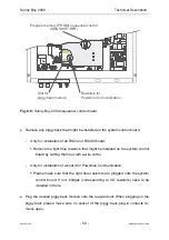
The Powerline piggy back modem is installed (see Fig. 6.6)

• 

The last digit of the system control software version is a two (VX.x2). 

• 

The blue resistors under the piggy back have to be installed for Powerline 

communication (see Fig. 6.6, page 59)

• 

For communication with the PC 

• 

A socket modem SWR-COM is available.  

• 

Some PCs are equipped with a 25-pole DSUB plug connector (e.g. COM2) in 

     terface. Then an RS232 adapter 25-pin (plug) to 9-pin (socket) is necessary  

     (order no. 36-5010).  

• 

The visualization software Sunny Data must be installed.  

How to install Powerline Communication 

• 

Powerline Communication with a PC  

The RS232 connector from the SWR-COM is plugged into a free COM port of 

the PC (COM1 … COM4). If necessary use the interface adapter DB9/DB25. 

The SWR-COM is plugged into the electricity socket. For details on the visuali-

zation software Sunny Data please see the Sunny Data manual.  

• 

Powerline Communication with a Sunny Boy Control  

Plug the 230V power cable of the Sunny Boy Control into the electricity socket. 

For operation of the Sunny Boy Control or Sunny Data Control for Sunny Boy 

Control please refer to the according manuals. 

Summary of Contents for Sunny Boy 2000

Page 1: ...SB2000 11 EE0101 Sunny Boy 2000 The Transformerless String Inverter for Photovoltaic Plants Version 1 2 Technical Description Sunny Boy 2000...

Page 2: ...Sunny Boy 2000 Technical Description SB2000 11 EE 2 SMA Regelsysteme GmbH...

Page 3: ...e the following description of symbols This indicates a feature that is important either for optimal and comfort able usage or optimal operation of the system Example Useful C routines for this purpos...

Page 4: ...3 3 1 Mains Connection 24 3 3 2 Connection of the PV panels 26 4 Commissioning 30 5 Operation and Failure Indication LEDs 31 6 Plant Monitoring and Diagnosis 48 6 1 Data Transmission via Powerline 48...

Page 5: ...Notice The Sunny Boy String Inverter may only be opened by qualified per sonnel for both installation and maintenance The device can still be charged with very high hazardous voltages even when disco...

Page 6: ...regulations of the employee association Berufsgenossenschaft f r Feinmechanik und Elektrotechnik concerning the Inde pendent Disconnection Device known as MSD Mains monitoring device with allo cated...

Page 7: ...ersion of the DC voltage from the PV panel to grid conform AC voltage with so called inverters and the subsequent con nection to the mains in the house distribution Here the solar energy system provid...

Page 8: ...SMA The String Inverter connects a small number of serially connected PV panels strings with the local electricity grid Even large PV systems can be created with this method the large PV system then...

Page 9: ...kWp with extended input voltage range Sunny Boy 2000 The transformerless String Inverter with extended input voltage range and ex cellent efficiency ideal for large PV plants Sunny Boy 2500 The most p...

Page 10: ...he signal transmission between the PC and the single inverters is normally done via Powerline communication see chapter 6 1 Data Transmission via Powerline The Sunny Boy String Inverters support the f...

Page 11: ...VPV IAC fAC VAC Fig 2 1 Block Circuit Diagram of Sunny Boy 2000 The string inverter s nominal power is dimensioned for the serial connection of a maximum of 20 modules with 36 to 40 cells each It is...

Page 12: ...ependent one chip microcomputers and fully complies with all grid feeding regulations of the VDEW and the employee associations MSD with evaluation of the grid impedance and GFCI The Sunny Boy therefo...

Page 13: ...ficially certified by the employee associations The device is a Selbstt tige Freischaltung f r Eigenerzeugungsanlagen einer Nennleistung 4 6 kVA mit einphasiger Paralleleinspeisung ber Wechselrichter...

Page 14: ...frequency exceeds a range of 0 2 Hz of nominal mains frequency fN with a mains voltage of 30 15 of nominal mains voltage this must additionally cause a mains disconnection within 0 2 s l Insulation T...

Page 15: ...onsuming disconnection device testing by the electricity company and the installer is not necessary The previously required periodic tests are not necessary Important arguments for the omission of rep...

Page 16: ...inverters can be dam aged in transit Please inspect your inverter thoroughly after it is delivered If any damages can be detected on the packaging that could make you conclude the contents is damaged...

Page 17: ...resulting directly or indirectly from faulty installation A suitable position must be found for the inverter s while the PV plant is designed It is important to take the following criteria into accou...

Page 18: ...Do not expose the string inverter to direct sunlight if necessary in stall a shading roof A minimum distance of 200 mm must be clear above the inverter for ventilation i e no cupboards ceiling etc Fre...

Page 19: ...ng at PV panels with the MultiContact plug connector system For PV panels where this plug system is not used SMA offers an adapter set SMA material no SWR1500 MC Sunny Boy 2000 Cable gland PG 16 with...

Page 20: ...2000 63 50 mm Fig 3 2 Drilling Template Preparing the Mounting The Sunny Boy is mounted on its back with three metal straps on a firm sur face Three screws and the corresponding dowels are necessary...

Page 21: ...y Boy against lifting up After the Sunny Boy has been hanged into the top screws fasten the bottom screw to secure against lifting up Mounting to the wall Mark the holes with the drilling template Dri...

Page 22: ...f the Sunny Boy and the connection to the input and output cabling must be done in the order described here Following this order the installer will make sure not to open contacts under load and exclud...

Page 23: ...nd receptacle connector care fully remove the green yellow cable in order to remove the front panel You can now see the position of relevant modules and clamps in the open case in front of you You wil...

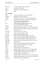
Page 24: ...capacitive discharges resulting in disconnection The installation of an additional RCB in the mains connection cable is therefore not advisable If the user wishes to install an additional RCB anyway...

Page 25: ...s Insert the according PG fastening into the case and secure it with a bolt from inside Strip the insulation off the end of the cable and insert it into the inverter The inverter is delivered with a p...

Page 26: ...tive MultiContact plug connectors at the bottom of the Sunny Boy Depending on the type of PV panels you must distinguish between connecting one single or two parallel strings In order to be able to co...

Page 27: ...his failure before continuing the installation Acquiring the electric resistance between protective earth PE and the plus and minus poles of the PV panel A low resistance 2 M shows there is a high res...

Page 28: ...unny Boy an electric potential to protective earth arises on the plus and minus lines equaling the PV panel voltage string voltage The monitoring of the isolation results in a minor electric connectio...

Page 29: ...rid Always disconnect the mains first The plug connectors can be damaged by an electric arc occurring when separating the PV panel while feeding to the grid In this case both parts of the relevant plu...

Page 30: ...he inverter is connected to The Sunny Boy will begin operation as soon as the input voltage is sufficient How much power the Sunny Boy feeds to the grid depends on the amount of PV power supplied by t...

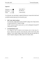
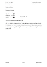
Page 31: ...mber of self test and safety proce dures which the user does not notice The user can obtain the inverters operating status from the three LEDs integrated in the lid See Table 5 1 Operation indication...

Page 32: ...schlu Earth Fault St rung Failure Photovoltaik Stringwechselrichter Photovoltaic string inverter SWR 2000 Fig 5 1 Partial front view of Sunny Boy 2000 Description for the following text LED off LED bl...

Page 33: ...hanging operating condition or manually initiated condition green red yellow waiting checking grid starting conditions are being checked green red yellow feeding grid MPP or constant voltage mode norm...

Page 34: ...input voltage is too low VPV approx 60 V to supply the inverter control system with enough power Initialization All LEDs are on The Sunny Boy control system is initializing The string voltage to the i...

Page 35: ...on is Waiting Stop condition can also be initiated by the user with the Sunny Boy Control or the PC program Sunny Data In this case the Sunny Boy inverter remains in this condi tion until set to MPP O...

Page 36: ...dently acquires the MPP voltage of the PV panel which is internally defined as PV setpoint voltage In MPP mode the maximum power point PAC is set by changing the required PV voltage at the PV panel Co...

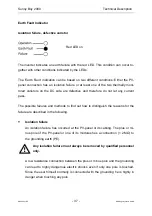
Page 37: ...d therefore do not let any current pass The possible failures and methods to find out how to distinguish the reasons for the failure are described in the following Isolation failure An isolation failu...

Page 38: ...tion is indicated with the Earth fault LED It is highly recommended to have qualified personnel exchange the thermally monitored varistors if necessary Determining the Failure The red LED indicates on...

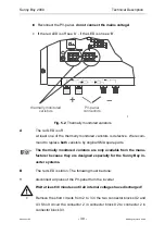
Page 39: ...defective We recom mend to replace both varistors by original SMA spare parts The thermally monitored varistors are only available from the manu facturer because they are designed especially for the S...

Page 40: ...verter is damaged and has to be repaired by the manufacturer If the LED is off the insulation of the inverter or the connection cabling is defec tive The failure must be detected with appropriate meas...

Page 41: ...ow LED on The yellow failure LED is permanently on This is a failure of the grid monitoring or the autonomous disconnection device MSD In an internal test the inverter has detected a failure in the di...

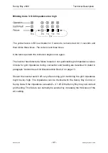
Page 42: ...llowing reasons Low grid voltage VAC min see Table 9 1 High grid voltage VAC max see Table 9 1 Low grid frequency fAC min see Table 9 1 High grid frequency fAC max see Table 9 1 Check the electric gri...

Page 43: ...a failure based on non permissible grid impedance values Criteria for grid impedance during connection and feeding are described in detail in paragraph Autonomous Grid Disconnection Device on page 13...

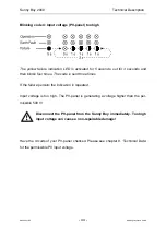
Page 44: ...four times The code is sent three times If the failure persists the indication is repeated Input voltage is too high The PV panel is generating a voltage higher than the per missible 500 V Disconnect...

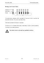
Page 45: ...n LED is activated for 5 seconds out for 3 seconds and then blinks five times The code is sent three times If the failure persists the indication is repeated The device is in a condition that makes it...

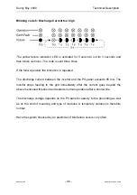
Page 46: ...s repeated The discharge current between the inverter and the PV panel exceeds 95 mA The inverter stops feeding to the grid immediately after the current goes beyond the above mentioned threshold and...

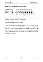
Page 47: ...persists the indication is repeated The Sunny Boy s monitoring systems have detected a differential current and imme diately disconnected the device from the grid The integrated all pole sensitive dif...

Page 48: ...COM This is already integrated in the Sunny Boy Control the specific controller for PV plants The PC or the Sunny Boy Control can be positioned anywhere within the in house network as they acquire da...

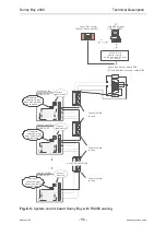
Page 49: ...unny Boy Sunny Boy Sunny Boy Sunny Boy Control SWR COM Sunny Boy Sunny Boy Sunny Boy PC PC Sunny Boy Control Powerline Powerline Powerline Fig 6 1 Example of data transmission via Powerline A detailed...

Page 50: ...ector e g COM2 in terface Then an RS232 adapter 25 pin plug to 9 pin socket is necessary order no 36 5010 The visualization software Sunny Data must be installed How to install Powerline Communication...

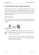
Page 51: ...can then be done with a separate data cable RS232 communication If only one Sunny Boy has to be connected to the PC the easiest way is direct cou pling via an RS232 port A maximum of 15 m is permissi...

Page 52: ...e PCs are equipped with a 25 pin DSUB plug connector In this case an RS232 adapter 25 pin plug to 9 pin socket adapter is necessary or der no 36 5010 Installation of the RS232 cable Work on the invert...

Page 53: ...ld Piggy Back socket Jumpers not mounted PC with DB9 plug in COM1 COM4 PC with DB25 plug in COM1 COM4 DB25 socket DB9 socket Shield connect shield to case light blue resistors removed PC PC or GND TXD...

Page 54: ...Fig 6 4 Schematic layout of RS485 data transmission with several Sunny Boys What do you need for RS485 communication a special RS485 piggy back module has been installed in all Sunny Boys the last di...

Page 55: ...emoved be removed Second Sunny Boy Last Sunny Boy First Sunny Boy RS485 RS232 interface converter SUB D 9 pin to SUB D 25 pin No 39 0020 PC with DB25 plug in COM1 or COM2 or 680 7 680 Connect shield t...

Page 56: ...or is connected by mounting a jumper no 1 jumper directly above the terminal strip Two resistors of 680 Ohm each must be integrated into the DB9 connection at the beginning of the cable that is connec...

Page 57: ...erfaces or the Powerline protocol In order to install a new interface in the Sunny Boy a corresponding piggy back mod ule has to be installed on the system control board Please follow all relevant ins...

Page 58: ...em you have to be on the same electric potential Discharge the electrostatic charge by touching the grounded case before touching an electronic component otherwise you run a great risk of destroying y...

Page 59: ...nstallation of an RS232 or RS485 board Remove the light blue resistors that might be installed on the system control board by cutting them out with a wire cutter Only for installation of a board for P...

Page 60: ...steme GmbH l Connect the green yellow PE cable to the lid and close the Sunny Boy with the lid Tighten all four screws l Reconnect the PV panel l Connect the inverter to the grid If enough PV power is...

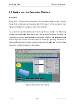
Page 61: ...features known under Windows The available measurement channels of the Sunny Boy see chapter 6 4 Measuring Channels and Messages of the Sunny Boy can be displayed online The data can be displayed man...

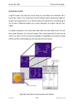
Page 62: ...sioning of the PV plant Additional features are remote diagnosis via modem and fax mes sages For global visualization of PV plant data SMA offers the Sunny Data Control PC soft ware under Windows E g...

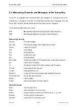
Page 63: ...ge of the internal Upv control Iac Ist current to the grid Uac grid voltage Fac grid frequency Pac power fed to grid Zac grid impedance Rerd Start isolation resistance of PV plant before connected to...

Page 64: ...K1 Schliess Relay K1 does not close correctly K1 Trenn Relay K1 does not separate correctly K2 Trenn Relay K2 does not separate correctly NUW UAC different values between BFR and SRR for grid voltage...

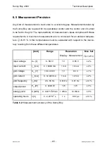
Page 65: ...ambient tempera ture U of 25 C Other temperatures must be evaluated with respect to the inaccu racy resulting from these different temperatures Unit Range Resolution Max fail Display Measurement U 25...

Page 66: ...ests We recommend to conduct the following steps in case your PV plant nonetheless does not operate correctly Check the blink code on the lid of the Sunny Boy and compare the code with the blink codes...

Page 67: ...lure If so how can you reproduce it Does the failure occur sporadically Has this failure always occurred What were the ambient conditions when the failure occurred Information concerning the PV module...

Page 68: ...livery but runs at least until the expiration of the original warranty period for the item delivered Evidence SMA will only render guaranty services if the objected device is sent back to SMA to gethe...

Page 69: ...of irregular consumers unshielded mo tors switching power supplies converters etc Furthermore the simulta neous operation of babyphones may lead to short time data transmission disturbances or interru...

Page 70: ...d string has to be within the specified input voltage range even in case of very low outside temperatures 10 C UMPP 70 C min input voltage The MPP voltage of the connected string must not exceed the s...

Page 71: ...ortion of output current KIAC 4 for KU AC 2 PAC 0 5 PACnom Phase shifting factor related to fundamental 0 Grid monitoring Vgrid fgrid Zgrid RISO I N MSD Mains monitoring with allocated Switching Devic...

Page 72: ...on Protection classification EN 60529 IP65 dust proof jet proof Size width x height x back to front ca 434 x 295 x 214 mm Weight ca 24 kg Certification EMC DIN EN 50081 part 1 EN 55014 EN 60555 part 2...

Page 73: ...GmbH Input Current of the Sunny Boy 2000 0 0 2 0 4 0 6 0 8 0 10 0 100 200 300 400 500 600 Vpv V Maximum output power of the Sunny Boy 2000 0 500 1000 1500 2000 100 200 300 400 500 600 Vpv V Fig 9 1 O...

Page 74: ...000 11 EE 74 SMA Regelsysteme GmbH Sunny Boy 2000 efficiency for different input voltages 80 0 85 0 90 0 95 0 100 0 0 10 20 30 40 50 60 70 80 90 100 110 Pac Pnom Pac Pdc Upv 400 V Upv 300 V Upv 200 V...

Page 75: ...4 UPV Stop V 100 500 110 Installer 5 T Stop S 1 300 2 Installer 6 Usoll Konst V 140 500 450 Installer 23 NiTest 0 1 1 Installer 28 Uac Min V 180 300 198 Installer 29 Uac Max V 180 300 251 Installer 3...

Page 76: ...2000 Technical Description SB2000 11 EE 76 SMA Regelsysteme GmbH 10 Appendices Appendix 1 Certificates for the Sunny Boy 2000 SMA Declaration of Conformity Clean Report of Findings by the employee as...

Page 77: ...Sunny Boy 2000 Technical Description SB2000 11 EE 77 SMA Regelsysteme GmbH...

Page 78: ...Sunny Boy 2000 Technical Description SB2000 11 EE 78 SMA Regelsysteme GmbH...

Page 79: ...Technical Description Powerline Communication Sunny Boy on the Internet http www SMA de For all users of SMA photovoltaic system components we have established a forum Sunny Box under http www sma de...

Reviews: