Sunny Boy 2000
Technical Description
SB2000-11:EE
- 56 -
SMA Regelsysteme GmbH
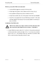
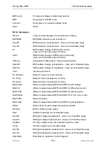
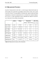
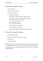
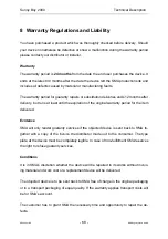
Installation of the RS485 cable
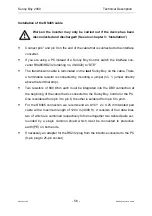
Work on the inverter may only be carried out if the device has been
disconnected and discharged! (See also chapter 3: ’Installation’)
•
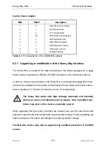
Connect pin 7 and pin 9 on the end of the cable that is connected to the interface
converter.
•
If you are using a PC instead of a Sunny Boy Control, switch the interface con-
verter RS485/RS232 (ordering no. 39-0020) to “DTE“.
•
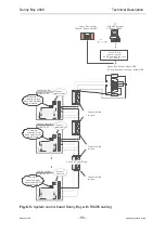
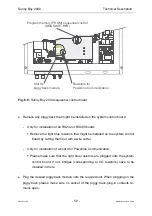
The transmission cable is terminated on the last Sunny Boy on the cable. There
a termination resistor is connected by mounting a jumper (no. 1, jumper directly
above the terminal strip).
•
Two resistors of 680 Ohm each must be integrated into the DB9 connection at
the beginning of the cable that is connected to the Sunny Boy Control or the PC.
One is soldered from pin 3 to pin 6, the other is soldered from pin 5 to pin 8.
•
For the RS485 connection we recommend an LIYCY 2 x 0.25 mm twisted pair
cable with a maximum length of 1200 m (4000 ft). It consists of four data lines
two of which are combined respectively to form altogether two twisted pairs sur-
rounded by a single common shield which must be connected to protective
earth (PE) on both ends.
•
If necessary an adapter for the RS232 plug from the interface converter to the PC
(9-pin plug to 25-pin socket)


