4 Product Overview
SMA Solar Technology AG
Operating manual
STP3-6-3AV-40-BE-en-13
19
Parallel Operation of the DC Inputs A and B
You have the option of operating the inverter DC inputs A and B in parallel. As a result, and as
opposed to normal operation, several parallel-connected strings can be connected to the inverter.
The inverter automatically detects the parallel operation of the DC inputs A and B.
SMA ShadeFix
The inverter is equipped with the shade management system SMA ShadeFix. SMA ShadeFix uses
an intelligent MPP tracking system to determine the operating point with the highest output during
shading conditions. With SMA ShadeFix, inverters use the best possible energy supply from the PV
modules at all times to increase yields in shaded systems. SMA ShadeFix is enabled by default. The
time interval of SMA ShadeFix is usually six minutes. This means that the inverter determines the
optimum operating point every six minutes. Depending on the PV system or shading situation, it may
be useful to adjust the time interval.
All-pole sensitive residual-current monitoring unit
The all-pole sensitive residual-current monitoring unit detects alternating and direct differential
currents. In single-phase and three-phase inverters, the integrated differential current sensor detects
the current difference between the neutral conductor and the line conductor(s). If the current
difference increases suddenly, the inverter disconnects from the utility grid.
SMA Smart Connected
SMA Smart Connected is the free monitoring of the inverter via the SMA Sunny Portal. Thanks to
SMA Smart Connected, the PV system operator and qualified person will be informed automatically
and proactively about inverter events that occur.
SMA Smart Connected is activated during registration in Sunny Portal. In order to use SMA Smart
Connected, it is necessary that the inverter is permanently connected to Sunny Portal and the data
of the PV system operator and qualified person is stored in Sunny Portal and up-to-date.
4.4
LED Signals
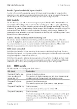
The LEDs indicate the operating state of the inverter.
LED signal
Explanation
The green LED is flashing
(two seconds on and
two seconds off)
Waiting for feed-in conditions
The conditions for feed-in operation are not yet met. As soon as the
conditions are met, the inverter will start feed-in operation.
The green LED flashes
quickly
Update of central processing unit
The central processing unit of the inverter is being updated.
The green LED is glowing
Feed-in operation
The inverter feeds in with a power of at least 90%.
The green LED is pulsing
Feed-in operation
The inverter is equipped with a dynamic power display via the green
LED. Depending on the power, the green LED pulses fast or slow. If
necessary, you can switch off the dynamic power display via the
green LED.
Summary of Contents for STP3.0-3AV-40
Page 106: ...www SMA Solar com ...

