background image

2  Safety

SMA Solar Technology AG

Installation Manual

7

EDMM-WAGO-IO-IA-en-11

2

Safety

2.1

Intended Use

The WAGO-I/O-SYSTEM 750 is used to receive digital and analog signals from sensors and output them to actuators.
The WAGO-I/O-SYSTEM 750 and the assembled I/O modules were developed for a working environment that
complies with the IP20 degree of protection. It is equipped with a finger guard and protection against solid foreign
objects ≥ 12.5 mm; however it is not protected against water.

In order to operate the product in potentially explosive atmospheres, corresponding enclosure protection is required in
accordance with the Directive 2014/34/EU. Furthermore, please note that a type examination certificate must be
obtained that confirms the correct installation of the system in the enclosure or switch cabinet.

The product is designed for indoor use only.

Use SMA products only in accordance with the information provided in the enclosed documentation and with the
locally applicable laws, regulations, standards and directives. Any other application may cause personal injury or
property damage.

Alterations to the SMA products, e.g., changes or modifications, are only permitted with the express written permission
of SMA Solar Technology AG. Unauthorized alterations will void guarantee and warranty claims and in most cases
terminate the operating license. SMA Solar Technology AG shall not be held liable for any damage caused by such
changes.

Any use of the product other than that described in the Intended Use section does not qualify as the intended use.

The enclosed documentation is an integral part of this product. Keep the documentation in a convenient, dry place for
future reference and observe all instructions contained therein.

This document does not replace and is not intended to replace any local, state, provincial, federal or national laws,
regulations or codes applicable to the installation, electrical safety and use of the product. SMA Solar Technology AG
assumes no responsibility for the compliance or non-compliance with such laws or codes in connection with the
installation of the product.

The type label must remain permanently attached to the product.

2.2

IMPORTANT SAFETY INSTRUCTIONS

SAVE THESE INSTRUCTIONS

This section contains safety information that must be observed at all times when working.

The product has been designed and tested in accordance with international safety requirements. As with all electrical
or electronical devices, there are residual risks despite careful construction. To prevent personal injury and property
damage and to ensure long-term operation of the product, read this section carefully and observe all safety
information at all times.

DANGER

Danger to life due to electric shock when live components or cables are touched

High voltages are present in the conductive components or cables of the product. Touching live parts and cables
results in death or lethal injuries due to electric shock.

• Do not touch non-insulated parts or cables.

• Disconnect the product from voltage sources and make sure it cannot be reconnected before working on the

device.

• Observe the prescribed minimum clearance between the network cable and live installation components, or

use suitable insulation.

• Observe all safety information on components associated with the product.

• Wear suitable personal protective equipment for all work on the product.

• Always perform all work in accordance with the locally applicable standards, directives and laws.

Summary of Contents for Modbus EDMM-10

Page 1: ...EDMM WAGO IO IA en 11 Version 1 1 ENGLISH Installation Manual WAGO I O SYSTEM 750 with SMA DATA MANAGER M...

Page 2: ...onsequential damages under any circumstances The exclusion of implied warranties may not apply in all cases under some statutes and thus the above exclusion may not apply Specifications are subject to...

Page 3: ...n the mounting rail 23 6 Connection 25 6 1 Overview of the Connection Area 25 6 2 Connecting the conductor the CAGE CLAMP 25 6 3 Information on shielding 26 6 4 Functional grounding 26 6 5 Voltage sup...

Page 4: ...ecting the device for configuring sensors 40 7 3 3 Defining the input and function for configuring sensors 40 7 3 4 Defining the channel and scaling for grid management services 44 7 3 5 Displaying me...

Page 5: ...Content and Structure of this Document This document supplements the documents that are enclosed with each product and does not replace any locally applicable codes or standards Read and observe all...

Page 6: ...mple bold Messages Terminals Elements on a user interface Elements to be selected Elements to be entered Connect the insulated conductors to the terminals X703 1 to X703 6 Enter 10 in the field Minute...

Page 7: ...umentation in a convenient dry place for future reference and observe all instructions contained therein This document does not replace and is not intended to replace any local state provincial federa...

Page 8: ...touch electronic components NOTICE Damage to the product due to cleaning agents The use of cleaning agents may cause damage to the product and its components Clean the product and any dirty contacts...

Page 9: ...ange any automatically generated passwords before initial commissioning This will reduce the risk of unauthorized persons gaining access to your system Regularly change your passwords This will reduce...

Page 10: ...en 11 10 3 Scope of Delivery Check the scope of delivery for completeness and any externally visible damage Contact your distributor if the scope of delivery is incomplete or damaged Figure 1 Componen...

Page 11: ...ly module 750 602 C 8 channel DC 24 V digital input terminal 750 1415 D 8 channel DC 24 V digital output terminal 750 1515 E 2 4 channel analog input terminal 2 TempIN PT100 750 464 F 4 channel analog...

Page 12: ...coupler is suitable for fieldbus communication with Modbus TCP A B C D E J F F G H I Figure 3 Fieldbus coupler configuration Position Designation A Labeling option with Mini WSB B Status LEDs C Data...

Page 13: ...t 1 B LINK ACT 2 green Indicates a connection to the physical net work at Port 2 C MS Red green Indicates the node status D NS Red green Indicates the network status Node status E OK Red green orange...

Page 14: ...F 8 Feed in Ground field sup ply For detailed information on evaluation of the LED statuses see Section 4 8 LED Signals page 16 4 4 I O modules Different sensors and actuators are connected to the WAG...

Page 15: ...n ensures correct data transmission via terminal bus The bus end terminal 750 600 is not equipped with any power contacts CAGE CLAMP connections or LED signaling 4 6 Hardware address MAC ID The WAGO I...

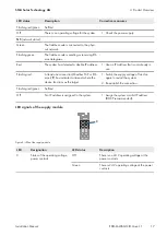
Page 16: ...oup LINK ACT 1 LINK ACT 2 MS and NS The two color LEDs MS module status and NS network status are only used by the Ethernet IP protocol The indications of these two LEDs comply with the Ethernet IP sp...

Page 17: ...hat is not already in use Flashing red At least one connection Modbus TCP or Eth ernet IP has indicated a timeout where the device functions as the target 1 Switch the supply voltage off and on again...

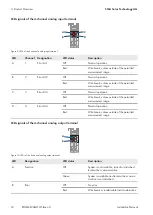
Page 18: ...the permitted measurement range C 3 Error AI 3 Off Normal operation Red Wire break values outside of the permitted measurement range D 4 Error AI 4 Off Normal operation Red Wire break values outside...

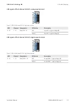
Page 19: ...rminal LED Channel Designation LED status Description A H 1 8 Status DI 1 8 Off Input DI 1 signal voltage 0 Green Input DI 1 signal voltage 1 LED signals of the 8 channel DC 24 V digital output termin...

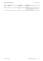
Page 20: ...e watchdog timer is enabled Green System is available and terminal bus commu nication is not disturbed C 1 Off No error Red Range violated values too high or too low short circuit or wire break D 2 Of...

Page 21: ...ct Overview SMA Solar Technology AG Installation Manual 21 EDMM WAGO IO IA en 11 LED Channel LED status Description H 4 Off No error Red Range violated values too high or too low short circuit or wire...

Page 22: ...n mount an additional end clamp under the fieldbus node to secure the fieldbus node against sliding down Properties of the mounting rail The WAGO I O SYSTEM 750 can be directly snapped onto a mounting...

Page 23: ...ulated assembly An assembly is insulated when it is designed so that there is no direct conductive connection between the cabinet frame or the machine parts and the mounting rail In this case the grou...

Page 24: ...SMA Solar Technology AG Installation Manual EDMM WAGO IO IA en 11 24 Press the product down onto the mounting rail from the top The product snaps audibly into place 2 Ensure that the product is secure...

Page 25: ...0 mA 6 2 Connecting the conductor the CAGE CLAMP The CAGE CLAMP connection is used to connect the conductor for system supply and supply of the various components of the I O modules The CAGE CLAMP con...

Page 26: ...in the event of disturbances that affect the signal cable You can directly connect the shielded cable to some of the I O modules Use the WAGO shield connection system for all others Improve the shiel...

Page 27: ...O SYSTEM 750 do not have any internal overcurrent protection For this reason a suitable overcurrent protection must be installed externally for every feed in for example using fuses The maximum permi...

Page 28: ...Regulated power supply units Stable grid supply cannot always be guaranteed anywhere all the time For this reason regulated power supply units must be used in order to guarantee the quality of the sup...

Page 29: ...s for direct connection of sensors with 2 conductor technology potential free contact The sensors are connected to the CAGE CLAMP connections DI 1 and 24 V to DI8 and 24 V For interference suppression...

Page 30: ...n 8 Dig In Figure 19 Example connection of the 8 channel DC 24 V digital input terminal 6 5 5 2 8 channel DC 24 V digital output terminal The 8 channel DC 24 V digital output terminal transmits binary...

Page 31: ...on A H 1 8 1 8 DO 1 8 Digital output 1 8 signal voltage I P 9 16 0 V Digital output 1 8 field supply 0 V 0 V 0 V 0 V 0 V 0 V 0 V 0 V DO DO DO DO DO DO DO DO 2 3 4 5 6 7 8 9 10 11 12 13 14 15 16 0 V 1...

Page 32: ...D and a rote error LED for each channel indicate either the operating state a short circuit a wire break or values outside the range of measurement PT100 sensors are connected to the CAGE CLAMP connec...

Page 33: ...ound The ground connections for all 4 channels are connected to one shared 0 V ground potential A red LED indicates a wire break or a value outside of the measurement range for each channel The intern...

Page 34: ...A to 20 mA The 4 channel analog output terminal 0 mA to 20 mA has four output channels and generates signals that must be strictly restricted to 4 mA to 20 mA by an internal scaling installed in Data...

Page 35: ...n Designation A 1 1 AO 1 Analog output 1 signal voltage B 2 Ground Analog output 1 ground C 2 3 AO 3 Analog output 3 signal voltage D 4 Ground Analog output 3 ground E 3 5 AO 2 Analog output 2 signal...

Page 36: ...rated network switch words in store and forward mode and supports a data transfer rate of 10 100 Mbit for every port as well as the full duplex half duplex and auto negotiation transfer modes The RJ 4...

Page 37: ...6 Connection SMA Solar Technology AG Installation Manual 37 EDMM WAGO IO IA en 11 Position Signal Designation D Not assigned E Not assigned F RD Receive data G Not assigned H Not assigned...

Page 38: ...dress selection switch is inactive in this position and the setting configured in the fieldbus coupler is used This means that the DHCP server is responsible for assigning the IP address 2 Switch the...

Page 39: ...he WAGO Ethernet Settings statistic IP address via the serial communication interface Use the address selections witch to set the value 0 position of the address switch 0000 0000 The address selection...

Page 40: ...ion and registered as a new Modbus device in Data Manager M During configuration a signal from 4 mA to 20 mA must be present at the analog inputs Procedure 1 Log in to the user interface of Data Manag...

Page 41: ...en 11 Procedure 1 Log in to the user interface of Data Manager M 2 Select the I O configuration menu item in the Configuration menu 3 Click the button to configure a new channel 4 Determine whether t...

Page 42: ...7 Commissioning SMA Solar Technology AG Installation Manual EDMM WAGO IO IA en 11 42 Figure 35 Example configuration solar irradiation...

Page 43: ...7 Commissioning SMA Solar Technology AG Installation Manual 43 EDMM WAGO IO IA en 11 Figure 36 Example configuration wind speed...

Page 44: ...Monitoring menu and check the information entered The newly added channel should now appear in the list and display the current values 7 3 4 Defining the channel and scaling for grid management servi...

Page 45: ...ew Modbus device in Data Manager M Procedure 1 Log in to the user interface of Data Manager M 2 Select the WAGO I O SYSTEM 750 in the list view in the SELECT DEVICE menu under the name that was assign...

Page 46: ...Figure 38 Example configuration 6 To create the channel as a setpoint source and as a percentage select the Current input input and the Percent channel 7 Fill out the input fields and confirm with Sav...

Page 47: ...s a power actual value fill out the input fields and confirm with Save 11 Review the added channels in the I O configuration menu 12 To assign the setpoint input to the previously configured input cha...

Page 48: ...make the settings according to the specifications required by the grid operator and laid down in the standards 16 Click on Save 17 To assign the actual value output at the previously configured outpu...

Page 49: ...setpoint for the active power limit of the nominal PV system power and one analog output channel should be created as the actual value of the power at the point of interconnection W Requirements The M...

Page 50: ...Manual EDMM WAGO IO IA en 11 50 6 Select the settings for the device and confirm with Save 7 Repeat the process to add additional sensors such as for example for cell temperature 8 Check the added se...

Page 51: ...via the I O LED The I O LED flashes red In the event of a local bus error the fieldbus coupler generates an error message error code and error argument A local bus error occurs for example when an I...

Page 52: ...Service Center www SMA Service com T rkiye SMA Service Partner DEKOM Telekom nikasyon A 90 24 22430605 SMA Online Service Center www SMA Service com France SMA France S A S Lyon 33 472 22 97 00 SMA O...

Page 53: ...8 Korea 82 2 520 2666 Argentina Brasil Chile Per SMA South America SPA Santiago de Chile 562 2820 2101 South Africa SMA Solar Technology South Africa Pty Ltd Cape Town 08600SUNNY 08600 78669 Internati...

Page 54: ...www SMA Solar com...

Reviews: