5 Mounting
SMA Solar Technology AG
Installation Manual
23
EDMM-WAGO-IO-IA-en-11
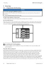
or bent. The base of the components extends into the profile of the mounting rail. For mounting rails with a height of
7.5 mm, mounting points (screw connections) must be countersunk under the node in the mounting rail (countersunk
screw or blind rivet). The metal springs on the bottom of the enclosure must have a low-impedance contact with the
mounting rail (widest possible contact surface).
Grounding the mounting rail
WARNING
Beware of electrical voltage
Ensure a proper electrical connection between the mounting rail and the frame or enclosure in order to guarantee
sufficient grounding and to avoid electric shock in the event of an error.
When assembling the frame, the mounting rail must be screwed onto the electrically conductive cabinet frame or
enclosure. The frame or enclosure must be grounded. The screw connection also establishes the electrical connection.
This grounds the mounting rail.
Insulated assembly
An assembly is insulated when it is designed so that there is no direct, conductive connection between the cabinet
frame or the machine parts and the mounting rail. In this case, the grounding must be established with an electrical
conductor in accordance with the valid national safety regulations.
Recommendation for optimal assembly
The optimal assembly involves a metallic mounting plate with a ground connection that has an electrically
conductive connection to the mounting rail.
5.2
Mounting the product on the mounting rail
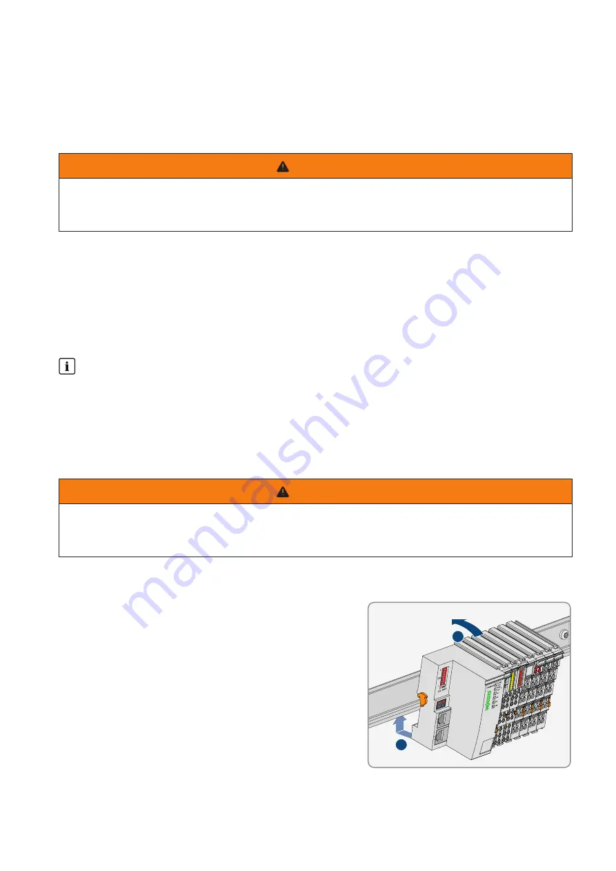
The WAGO-I/O-SYSTEM 750 comes pre-configured and is directly snapped onto the mounting rail as a complete
unit. A tongue and groove system is used for secure positioning and connection. Automatic locking guarantees secure
hold on the mounting rail.
WARNING
Beware of electrical voltage
Ensure a proper electrical connection between the mounting rail contact and the mounting rail in order to guarantee
sufficient grounding and to avoid electric shock in the event of an error. Observe the properties of the mounting rail.
Procedure:
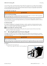
1. Attach the product to the mounting rail.
• Place the lower edge of the product onto the mounting rail.
1
2
Summary of Contents for Modbus EDMM-10
Page 54: ...www SMA Solar com...


