background image

 13

5926

19

2021

-

SXP35 & SXP50

SX Spacer

Follow the installation of the SX thruster in the 

Motor Installation 

to step 3

see next page

1.     Defi ne the location to install the thruster. 

(NB: Ensure the thruster does not protrude past the transom profi le on any side and there is no 

obstruction to the thrusters water flow. Also, check internally the thruster will not obstruct any objects.) 

2.     Mark the locations of the three drill holes using the defi ned measurements in this manual or from a template. 

(NB: Maximum hull thickness is 

50mm including optional spacer or 150mm for extended hull thickness models.)

3.    Drill main hole, then two support bolt holes. Clean the area from dust for installation of the thruster. 

(NB: Hull holes must be drilled fi rst before 

attaching the spacer as the top support holes are larger than the spacers.)

---------

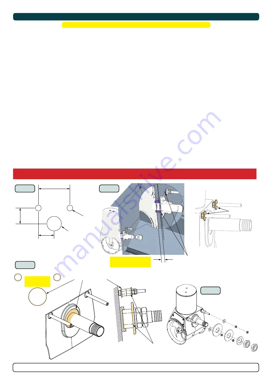
4.    Drill out the two support bolt holes in the spacer. 

5.     Apply MS Polymer sealant or equal to the back surface face of the spacer.

6.   Place the spacer to the hull.

Continue the installation of the SX thruster from step 4 in the 

Motor Installation.

MC_0074

!

 Please refer to the graphic for special considerations relating to your model 

!

IMPORTANT 

If using the 50mm spacer ensure you have the extended tube SX model.

MG_0262

Hull

Hull

12mm 

Spacer

Apply MS Polymer sealant or 

equal to back surface face

50mm 

Spacer

Drill

8.5 / 9 mm

Drill

8.5 / 9 mm

4

6

5

IMPORTANT 

The spacer and hull have different hole 

diameters for the support bolts. This is to 

allow the compression rings to be inserted 

into the hull only.

The spacer and hull for the main tube have 

the same hole diameter so compression 

rings can be inserted for the total length of 

the hole.

Compression 

ring

Compression 

ring

MG_0113

130 mm

5,12”

65 mm

2,56”

35,80 mm

1,41”

50 mm

1,97”

Drill holes in hull

Hole size 

for hull

Sealant (MS Polymer)

Thruster and attachment bolts

18 mm

0,71”

All rings need

+10% compression

All rings need

+10% compression

Bolt and Washer

Hull thickness

Maximum hull thickness 

is 50 mm or 150mm

Cover the 

entire surface

1 - 3

6

7 - 8

4 - 5

Motor Installation

1.     Defi ne the location to install the thruster. 

(NB: Ensure the thruster does not protrude past the transom profi le on any side and there is no 

obstruction to the thrusters water flow. Also, check internally the thruster will not obstruct any objects. Ensure cables internally do not obstruct 

any objects. Do not place cables or control box close to high heat radiating parts EG. Turbo/ exhaust manifolds etc.)

2.     Mark the locations of the three drill holes using the defi ned measurements in this manual or from a template. 

(NB: Maximum hull thickness is 

50mm including optional spacer or 150mm for extended hull thickness models.)

3.    Drill main hole, then two support bolt holes. Clean the area from dust for installation of the thruster.

4.     Install a bolt and washer to ensure top bolts contact surface area is level with the main tube. Temporally place the thruster through the holes to 

ensure correct fi tting. Using the cable leads from the thruster defi ne the location within the vessel for the installation of the control box. 

(NB: If 

using a spacer the support bolt and washer are not required.)

5.   Check the length of the compression rings. Compression rings must be longer than hull thickness to allow for compression 

(NB: Cut compression


sealants to length top achieve 10% compression.)

6.     The thruster assembly must sit flush on the transom. Grind and sand the area if required to ensure a secure fi t. 

(NB: Use caution when grinding/ 

sanding surfaces as to not remove too much fi breglass.)

7.     Ensure both bolts and washers to the support bars on the thruster are attached. 

Apply a sealant (MS Polymer) to:


- the inside surface of the cut-out holes on the hull. 


-To the surface of the washer to the thread and 


- in the recess of the main tube to the thread.


- 1cm deep inside all compression ring.  

place all compression rings to bolt threads. 

(NB: Ensure ample sealant (MS Polymer) around the bolts and centre tube for a watertight fi tting.)

8.   Insert the thruster with compression rings into the hole.

9.   Fasten the thruster


MC_0074

!

 Please refer to the graphic for special considerations relating to your model 

!

For installations in high corrosive environments (saltwater) the exposed aluminium parts of the thruster must be coated with an epoxy primer 

before antifouling or/and use.

Summary of Contents for SXP35

Page 1: ...LEIPNER AS P O Box 519 N 1612 Fredrikstad Norway www sleipnergroup com DOCUMENT ID REVISION DATE LANGUAGE Installation Guide For Pro DC External Electric Thruster Models SXP35 SXP50 EN I M 5926 19 202...

Page 2: ...he Stern Thruster 7 Stern Thruster Cowls Grids 8 Thruster Installation Instructions Thruster Installation Considerations and Precautions 10 Grids or Cowls Assembly 11 Tunnel Installation 12 Motor Inst...

Page 3: ...ide the boat like steerage links etc NB It is possible to mount the tunnel offset from the boat s centre line if necessary Heat protection cut off is calculated from the thruster motor To avoid cable...

Page 4: ...nch H Motor Height 374 14 72 374 14 72 W Width 183 7 20 183 7 20 L Length 171 6 7 171 6 7 L Standard tube length 108 4 3 108 4 3 L Extended tube length for thicker hulls 276 10 9 276 10 9 a Height of...

Page 5: ...lapse device protects against sudden change of drive direction The electric thermal cut off switch in electro motor protects against overheating auto reset when electro motor cools down Original Slei...

Page 6: ...SX35 SX50 Operation volts 12v 12v Max Current 250A 380A Duty Cycle S2 S2 Max ambient temp 50 c 50 c Min ambient temp 25 c 25 c Power supply cable 35 70mm AWG 2 00 35 70mm AWG 2 00 Mount direction Any...

Page 7: ...turb the water flow under the hull At higher speeds if the thruster is installed to low can cause damage to the thruster additional drag and unwanted water splashing Alignment The thruster can be inst...

Page 8: ...ooth inner walls for optimal water flow and strength A standard Sidepower stern thruster tunnel with add on cowls for shallow installation cowls to change the water flow direction to avoid obstruction...

Page 9: ...e thruster Ensure there is enough space both inside and outside the transom of the boat and the thruster does not get in conflict with existing equipment inside the boat like steerage links etc NB It...

Page 10: ...074 Grids or Cowls assembly 1 Attach the cowls or grids with included bolts and washers NB If installion of the cowls ensure the appropriate twist of the cowl to direct water away from obstacles MG_01...

Page 11: ...2 Tunnel Installation 1 Ensure to remove the plasic cover guard on the tunnel 2 Connect both ends of the tunnel to the thruster motor All hooks must be completely interlocked making the inside of the...

Page 12: ...ttaching the spacer as the top support holes are larger than the spacers 4 Drill out the two support bolt holes in the spacer 5 Apply MS Polymer sealant or equal to the back surface face of the spacer...

Page 13: ...lly place the thruster through the holes to ensure correct fitting Using the cable leads from the thruster define the location within the vessel for the installation of the control box NB If using a s...

Page 14: ...nal slot in the propeller 2 Insert the washer to the end of the shaft spline Tighten with the propeller lock nut 3 Apply anti fouling to the gear leg and propeller Do not apply anti fouling to any rub...

Page 15: ...nd drill the holes 3 Attach cables to the control box NB the control box internal components can be removed via its attachment screws for easier installation using thick battery cables 4 Tighten hose...

Page 16: ...the electrical operation of the vessel when not on board or in emergencies NB It is advised to install a fuse on the positive cable for protection against short circuiting of the main cables The fuse...

Page 17: ...1 Thruster A2 Temp switch NC NTC Temp switch NC NTC BLUE HOSE SX50 CONTROL BOX SX35 CONTROL BOX B B Tighten to 5 6 NM 4 13 lb ft Blue Hose Blue Hose Tighten to 5 NM 3 69 lb ft Tighten to 5 NM 3 69 lb...

Page 18: ...0 2 x 2 0 35 140 12 V 245 A DIN 200 SAE 380 EN 330 ANL 150 mm2 35 50 50 70 70 95 95 120 120 2 x 70 2 x 70 2 x 95 AWG 2 1 0 1 0 2 0 2 0 3 0 3 0 4 0 4 0 2 x 2 0 2 x 2 0 2 x 3 0 50 1400 12 V 370 A DIN 3...

Page 19: ...play and require no additional configuration setup See the Control panel manual for more information MC_0041 Please refer to the graphic for special considerations relating to your model MG_0127 Autom...

Page 20: ...as short as practically possible POWER Cable Must be one in each system length 2 5m 4 Port T Connector The 4 port T connector allows multiple spur cables to be connected NB Comes with two sealing caps...

Page 21: ...cut out is jagged or chipped use a sealant to assist the gasket 3 Place the gasket to the back face of the panel 4 Plug cables into the connectors at the rear of the control panel 5 Insert the contro...

Page 22: ...n switch size No water leakage around hull penetrated studs Check that there is no electrical connection between the electro motor body and positive terminal on the motor and between the electro motor...

Page 23: ...ed to the Purchaser at the Warrantor s expense If on the other hand the claim is determined to result from circumstances such as described in section 4 above or a result of wear and tear exceeding tha...

Page 24: ...ccuracies or omissions it may contain Continuous product improvement may change the product specifications without notice Therefore Sleipner Motor AS can not accept liability for any possible differen...

Reviews: