Sleipner SR-V300 Installation Manual Download Page 22

22

5927

7

2021

-

SRP 300


MG_0063

GASKET   

4x SCREWS 

58 mm

67 mm

125 mm

116 mm

132.7 mm

75.7 mm

Ø 4.5 mm

Ø 4.5 mm

Ø 4.5 mm

Ø 4.5 mm

(S-link)

External alarm buzzer

12V / 24V DC - max 0,5A

External alarm / buzzer connection

Supply

+ 12V / 24V DC 

-

+

Ø 4.5 mm

Rear

side

of pa

nel

Internal

fuse / relay

MG_0108

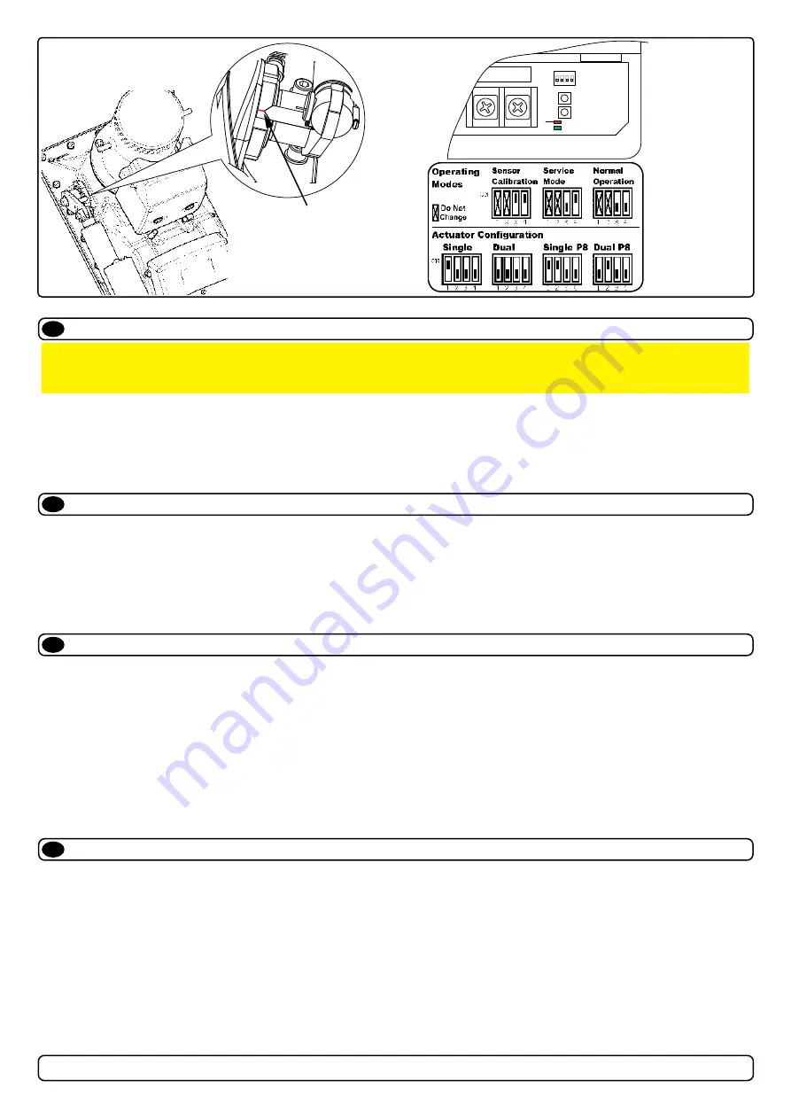
Align pointer on lever

arm with red mark on

bearing

Actuator arm and bearing

Controller

SETTINGS

UP
DOWN

FAULT

STATUS

(FUSE)

ON

1   2   3   4

MC_0069

MC_0069

MC_0069

MC_0069

Check drive shaft alignment

Calibrate drive shaft alignment

Actuator Confi guration

LED Indication

EN

EN

EN

EN

1) Connect power to thruster and S-link system. 
2) Sett DIP-switch on the controller to 0000. 
3) Turn on the panel. (The drive shaft deploys.)
4) The actuator lever arm and the bearing are set to alignment marking 
5) If marks align, turn panel off. Drive shaft retracts. 
6) If the marks do not align, proceed to calibrate drive shaft.

(NB: The drive shaft is correctly aligned when manufactured)

1) With dip-switches select ‘Service Mode’.
2) Align the arrow on the actuator arm with the calibration mark, using the UP/DOWN buttons.
3) With dip-switches select ‘Sensor Calibration Mode’.
4) Press and hold both UP and DOWN buttons until  STATUS LED light up green.

(NB: If FAULT LED light-up red, then the calibration is out of position (wrong align mark).

5) With dip-switches select ‘Operation Mode’, thruster retracts.

Dip-switch number 1 & 2 confi gures the actuator(s).

No.1 set to OFF when the retract has two actuators.
No.1 set to ON when the retract only has one actuator.

No.2 set to OFF when the retract does not have P8 type actuator(s).
No.2 set to ON when the retract has the P8 type actuator(s).
If dip-switch no.2 is set to ON and the actuator gives a rattling noise when the door closes, then there probably is not P8 actuator(s) and dip-switch 

no.2 needs to be set to OFF.
The actuator is a P8 type:
-If the actuator has a plastic cap at the back where you can adjust the actuator manually. 
-If it is marked with a sticker with P8 
-If the manufacturer label says P8

Continuous red light:


Motor over-temp, Controller over-temp, Controller no communication, Motor relay failure, Low battery voltage, Position sensor failure, No 

power     to actuators, Retractable unit failure, Temp sensor open circuit.

Flashing red light:


Red light fast blinking: Dip-switch in an invalid position.


Red light short flash every 2 seconds: Shaft not calibrated, or shaft calibrated out of range.

Continuous green light:


Normal mode, Service mode (actuators operated by UP/DOWN buttons). 


Re-calibrated “down”-position.

Flashing green light:


No S-Link communication.

IMPORTANT 

Before the thruster motor is operated, check the drive shaft alignment is completely straight when it reaches the end position form the control 

panel operation: 

Summary of Contents for SR-V300

Page 1: ...SLEIPNER AS P O Box 519 N 1612 Fredrikstad Norway www sleipnergroup com DOCUMENT ID REVISION DATE LANGUAGE Installation Guide For Pro Electric Retractable Thruster Models SRP V300 EN I M 5927 7 2021...

Page 2: ...nsiderations and Precautions 7 Marking and Trimming of SRF Flange 8 Installation Pre check 9 Required Modifications After Pre check 10 SRF Flange Installation 11 Motor House Installation 12 Hatch Inst...

Page 3: ...r at close range to easily flammable objects as it will reach over 100 C before the temperature switch is activated Do not store items close to the thruster motor as it can reach 100 C Any loose items...

Page 4: ...mentary measurement Height 172 6 77 H Motor housing height 452 17 80 MH SRF flange height 115 4 53 RD Retracted hatch supplementary measurement 445 17 52 ID Tunnel diameter 300 11 81 W SRF flange moto...

Page 5: ...n Flexible coupling between electro motor and drive shaft protects electro motor and gear system if propeller jams Original Sleipner panels shut off automatically 6 minutes after last use Original Sle...

Page 6: ...r the waterline The thruster while retracted must not conflict with any other component of the vessel such as stern drives propellers trim tabs or rudders Therefore stern installations do not require...

Page 7: ...oducts or via a Sleipner supplied interface product made for interfacing with other controls Any attempt to directly control or at all connect into the S link control system without the designated and...

Page 8: ...uster considering space required for installation operation and future maintenance 2 Mark the keel centre line on the inside of the hull Flip the SRF flange upside down and use the internal surface to...

Page 9: ...the label on actuators for correct voltage to the 6 mm cables on the terminals on the controller Set switch no 4 on the DIP switch marked SETTINGS to ON Remove the wooden safety part located above th...

Page 10: ...nge and motor stable 3 Open and close the hatch multiple times to ensure Clearance from the hull and hatch while open Hatch closes flush with the hull and extra force is still transferred to the hull...

Page 11: ...xy and breglass cutting or similar which laminating material is the actual boat builders responsibility Cover the upper part if grinding is necessary After moulding material have cured run the retract...

Page 12: ...lue is compatible with SRF and thruster case materials 2 Place the upper thruster Housing down on the SRF flange 3 Insert and fasten bolts Start with the 4 corner bolts followed by the remaining to re...

Page 13: ...cessive material before coating the hatch 9 Apply ller on to tunnel rings contact surface so the hatch will be secured properly Now re install hatch in its correct position Tighten bolts so hatch will...

Page 14: ...llation later 2 Fasten the bolts holding the motor to the motor bracket with the above torque 3 Check the drive shafts engage by rotating the propeller It is required the propeller can rotate via hand...

Page 15: ...ube has no loops and forms an airlock to stop the oil flow Ensure the oil tube angle is suf cient to allow oil to flow freely into the gear leg 3 Fill the oil tank with the same gear oil used in the g...

Page 16: ...ff the thruster independently from the rest of the electrical operation of the vessel when not on board or in emergencies NB It is advised to install a fuse on the positive cable for protection agains...

Page 17: ...AWG 2 0 2 0 4 0 2 x 2 0 2 x 3 0 2 x 3 0 2 x 4 0 2 x 4 0 2 x 4 0 24 V 280 A DIN 300 SAE 570 EN 520 ANL 250 mm2 35 35 35 50 50 70 70 95 95 120 120 2 x 95 AWG 2 2 2 1 0 1 0 2 0 2 0 3 0 3 0 4 0 4 0 2 x 3...

Page 18: ...automatic main switch Setup with manual main switch Controller M 12V 5A red black yellow Terminator 120 ohm Terminator 120 ohm Retract panel Power supply cable Retract thruster Controller 6 1242 T con...

Page 19: ...s short as practically possible POWER Cable Must be one in each system length 2 5m 4 Port T Connector The 4 port T connector allows multiple spur cables to be connected NB Comes with two sealing caps...

Page 20: ...20 5927 7 2021 SRP 300 MG_0136 EN Visual Wiring Diagram...

Page 21: ...21 5927 7 2021 SRP 300 MG_0137 EN Visual Wiring Diagram...

Page 22: ...uator s No 1 set to OFF when the retract has two actuators No 1 set to ON when the retract only has one actuator No 2 set to OFF when the retract does not have P8 type actuator s No 2 set to ON when t...

Page 23: ...cut out is jagged or chipped use a sealant to assist the gasket 3 Place the gasket to the back face of the panel 4 Plug cables into the connectors at the rear of the control panel 5 Insert the control...

Page 24: ...house and propeller but NOT anodes sealing rubber ttings or propeller shafts Propeller is fastened correctly to the shaft Propeller turns freely in tunnel The anode and or holding screw is tightened w...

Page 25: ...e Purchaser at the Warrantor s expense If on the other hand the claim is determined to result from circumstances such as described in section 4 above or a result of wear and tear exceeding that for wh...

Page 26: ...26 5927 7 2021 SRP 300 MC_0037 Notes EN...

Page 27: ...27 5927 7 2021 SRP 300 MC_0037 Notes EN...

Page 28: ...accuracies or omissions it may contain Continuous product improvement may change the product speci cations without notice Therefore Sleipner Motor AS can not accept liability for any possible differen...

Reviews: