Sleipner SE-IP100 Installation Manual Download Page 19

 19

2653

11

2021

-

SE IP 100 & SE IP 130

Electrical Specifi cations

MC_0044


*V

alid for DC motors

Model Size

System  Voltage

Nominal  current 

draw

Min. battery 

CCA

Rec. fuse

<7m total + & -

7-14m total + & -

15-21m total + & -

22-28m total + & -

28-35m total + & -

36-45m total + & -

Min.

Rec.

Min.

Rec.

Min.

Rec.

Min.

Rec.

Min.

Rec.

Min.

Rec.

*20/1

10S

12 V

150 A

DIN: 200  SAE: 380  EN: 330

ANL

 150

mm2

25

35

35

50

50

70

70

95

95

95

120

2 x 70

AW

G

3

2

2

1/0

1/0

2/0

2/0

3/0

3/0

3/0

2 x 4/0

2 x 2/0

*25/1

10S

12 V

200 A

DIN: 200  SAE: 380  EN: 330

ANL

 150

mm2

25

35

50

50

70

70

95

95

120

120

2 x 70

2 x 70

AW

G

3

2

1/0

1/0

2/0

2/0

3/0

3/0

4/0

4/0

2 x 2/0

2 x 2/0

*30/125S *30/140

12 V

245 A

DIN: 200  SAE: 380  EN: 330

ANL

 150

mm2

35

50

50

70

70

95

95

120

120

2 x 70

2 x 70

2 x 95

AW

G

2

1/0

1/0

2/0

2/0

3/0

3/0

4/0

4/0

2 x 2/0

2 x 2/0

2 x 3/0

*40/125S *40/140

12 V

315 A

DIN: 300  SAE: 570  EN: 520

ANL

 250

mm2

35

50

70

95

95

120

120

2 x 70

2 x 95

2 x 95

2 x 120

2x 120

AW

G

2

1/0

2/0

3/0

3/0

4/0

4/0

2 x 2/0

2 x 3/0

2 x 3/0

2 x 4/0

2 x 4/0

*50/140S

12 V

370 A

DIN: 350  SAE: 665  EN: 600

ANL

 325

mm2

50

50

70

95

120

2 x 70

2 x 70

2 x 95

2 x 95

2 x 120

2 x 120

2 x 120

AW

G

1/0

1/0

2/0

3/0

4/0

2 x 2/0

2 x 2/0

2 x 3/0

2 x 3/0

2 x 4/0

2 x 4/0

2 x 4/0

24 V

170 A

DIN: 175  SAE :332  EN: 280

ANL

 150

mm2

25

25

25

35

35

50

35

50

50

70

70

70

AW

G

3

3

3

2

2

1/0

2

1/0

1/0

2/0

2/0

2/0

*60/185S *60/140

12 V

370 A

DIN: 350  SAE: 665  EN: 600

ANL

 325

mm2

50

50

70

95

120

2 x 70

2 x 70

2 x 95

2 x 95

2 x 120

2 x 120

2 x 120

AW

G

1/0

1/0

2/0

3/0

4/0

2 x 2/0

2 x 2/0

2 x 3/0

2 x 3/0

2 x 4/0

2 x 4/0

2 x 4/0

24 V

170 A

DIN: 175  SAE: 332  EN: 280

ANL

 150

mm2

25

25

25

35

35

50

35

50

50

70

70

70

AW

G

3

3

3

2

2

1/0

2

1/0

1/0

2/0

2/0

2/0

*80/185T

12 V

530 A

DIN: 550  SAE: 1045  EN: 940

ANL

 400

mm2

70

70

120

2 x 70

2 x 95

2 x 95

2 x 120

2x 120

2 x 120

NA

NA

NA

AW

G

2/0

2/0

4/0

2 x 2/0

2 x 3/0

2 x 3/0

2 x 4/0

2 x 4/0

2 x 4/0

24 V

280 A

DIN: 300  SAE:570  EN: 520

ANL

 250

mm2

35

35

35

50

50

70

70

95

95

120

120

2 x 95

AW

G

2

2

2

1/0

1/0

2/0

2/0

3/0

3/0

4/0

4/0

2 x 3/0

*100/185T

12 V

740 A

DIN: 750  SAE: 1425  EN: 1320

ANL

 500

mm2

95

95

2 x 70

2 x 95

2 x 120

NA

NA

NA

NA

NA

NA

NA

AW

G

3/0

3/0

2 x 2/0

2 x 3/0

2 x 4/0

24 V

340 A

DIN: 400  SAE: 760  EN: 680

ANL

 325

mm2

50

50

50

70

70

95

95

120

120

2 x 95

2 x 95

2 x 120

AW

G

1/0

1/0

1/0

2/0

2/0

3/0

3/0

4/0

4/0

2 x 3/0

2 x 3/0

2 x 4/0

*120/215T

24V

420 A

DIN: 450  SAE: 855  EN: 760

ANL

 325

mm2

70

70

70

70

70

95

95

120

120

2 x 70

2 x 70

2 x 95

AW

G

2/0

2/0

2/0

2/0

2/0

3/0

3/0

4/0

4/0

2 x 2/0

2 x 2/0

2 x 3/0

*130/250T

12V

800 A

DIN: 750  SAE: 760  EN: 680

ANL

 500

mm2

95

95

2 x 95

2 x 95

2 x 120

2 x 120

NA

NA

NA

NA

NA

NA

AW

G

3/0

3/0

2 x 2/0

2 x 3/0

2 x 4/0

2 x 4/0

24V

350 A

DIN: 400  SAE: 760  EN: 680

ANL

 325

mm2

50

50

50

70

70

95

95

120

120

2 x 70

2 x 95

2 x 95

AW

G

2

1/0

1/0

2/0

2/0

3/0

3/0

4/0

4/0

2 x 2/0

2 x 3/0

2 x 3/0

*150/215T

24V

610 A

DIN: 560  SAE: 1064  EN: 940

ANL

 500

mm2

70

70

95

95

120

120

2 x 70

2 x 95

2 x 95

2 x 120

2 x 120

2 x 120

2/0

2/0

3/0

3/0

4/0

4/0

2 x 2/0

2 x 3/0

2 x 3/0

2 x 4/0

2 x 4/0

2 x 4/0

*170/250

24V

550 A

DIN: 560  SAE: 1064  EN: 940

ANL

 400

mm2

70

70

70

95

95

120

120

2 x 95

2 x 95

2 x 95

2 x 120

2 x 120

AW

G

2/0

2/0

2/0

3/0

3/0

4/0

4/0

2 x 3/0

2 x 3/0

2 x 3/0

2 x 4/0

2 x 4/0

*210/250

24V

500 A

DIN: 560  SAE: 1330  EN: 940

ANL

 400

mm2

70

70

70

95

95

120

120

2 x 70

2 x 70

2 x 95

2 x 95

2 x 120

AW

G

2/0

2/0

2/0

3/0

3/0

4/0

4/0

2 x 2/0

2 x 2/0

2 x 3/0

2 x 3/0

2 x 4/0

*250/300

24V

610-670 A

DIN: 700  SAE: 1330  EN: 1

170

ANL

 500

mm2

70

70

95

120

120

2 x 95

2 x 95

2 x 95

2 x 95

2 x 120

2 x 120

2 x 120

AW

G

2/0

2/0

3/0

4/0

4/0

2 x 3/0

2 x 3/0

2 x 3/0

2 x 3/0

2 x 4/0

2 x 4/0

2 x 4/0

*300/300

24*2

400-450A


(48V)

DIN: 400  SAE: 760  EN: 680

ANL

 325

mm2

50

70

50

70

70

95

95

120

120

120

140

NA

48V

AW

G

1/0

2/0

1/0

2/0

2/0

3/0

3/0

4/0

4/0

4/0

4/0

MG_0035

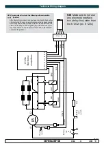
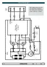
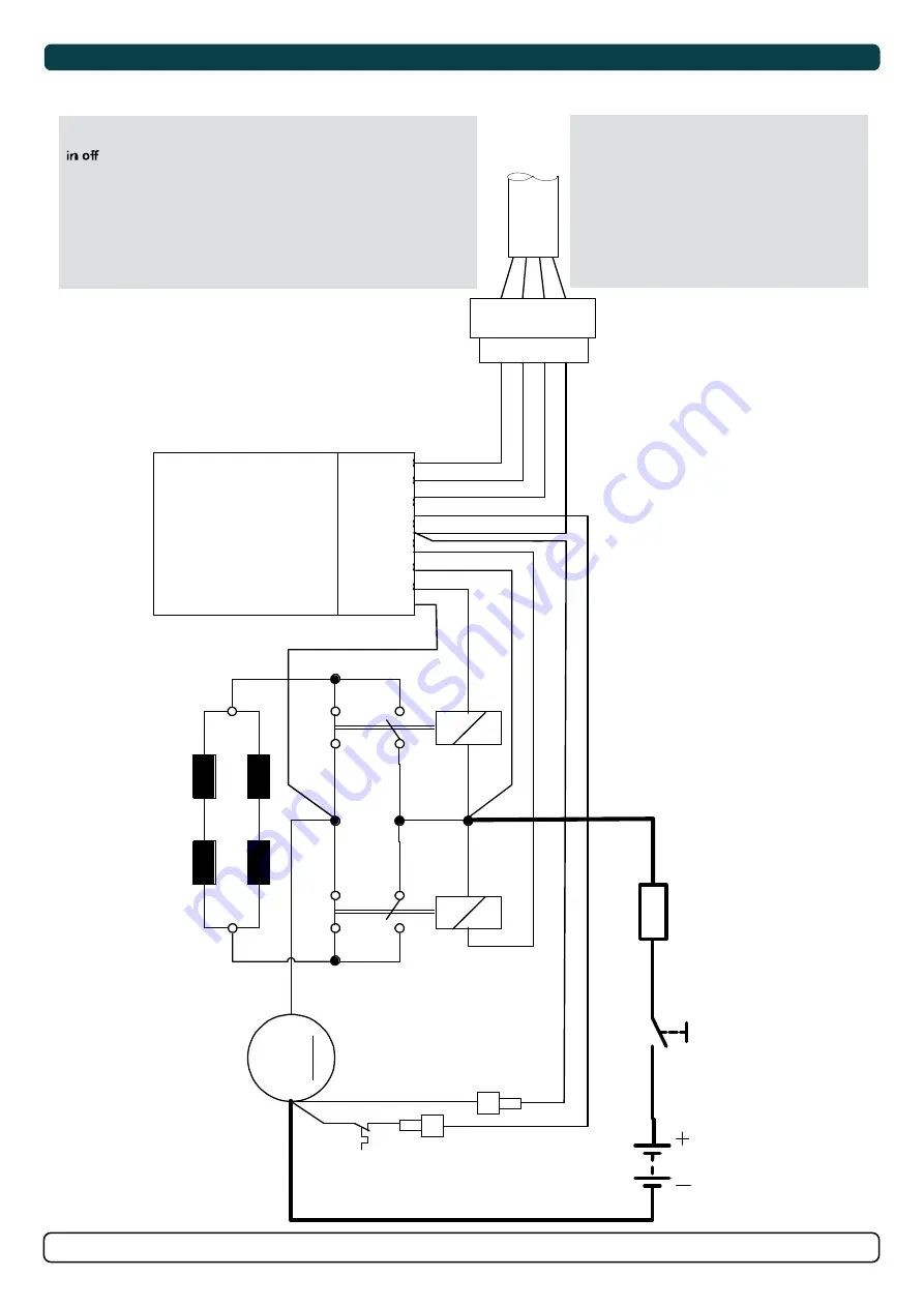
Technical Wiring Diagram

A2

A

1

Fu

se

re

d

gr

ey

bl

ue

bl

ac

k

gr

ey

bl

ue

br

own

re

d

6 1

23

2i

El

ect

ro

ni

c

con

tr

ol b

ox

Th

er

m

al

swi

tc

h

Ba

tt

er

y

12

V

or

24

V

Ba

tt

er

y

m

ai

n

sw

itc

h

M

4

3 2 1

3

4

2

1

8

6

9

5

re

d

re

d

bl

ac

k

7

whi

te

NB! 

Make sure to not use

any electronic interface

box (delay box) older than

the 6 1232i (ex. 6 122x)

on SP75Ti, SP95Ti, and

SP125Ti.

NB! 

Make sure to not use 

any electronic interface 

box (delay box) older than 

the 6 1232i (ex. 6 122x)

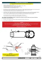
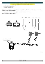
NB! Very important to check the following with main-switch 

   position:

  After all electrical connections have been completed check with an 

  ohm meter that there is no electrical connection between electro- 

  motor body and positive terminal on the motor and between the  

  electro motor body and the negative (A1) terminal on the motor.  

  If you feel unsure on how to perform this check, contact skilled  

  personnel for guidance. 

Summary of Contents for SE-IP100

Page 1: ...ER AS P O Box 519 N 1612 Fredrikstad Norway www sleipnergroup com DOCUMENT ID REVISION DATE LANGUAGE Installation Guide For Ignition Protected DC Electric Thruster Models SE IP100 SE IP130 EN I M 2653 11 2021 ...

Page 2: ...Thruster Specifications 5 Technical Specifications 5 Positioning of the tunnel thruster 6 Tunnel Length 7 Tunnel installation in sail boats 8 Water Deflection 9 Tunnel ends 10 Tunnel installation 11 12 Stern tunnel installation 13 Gear Leg Motor Bracket Installation 14 Propeller Installation 15 Motor Installation 16 Thruster Electrical Installation 17 Electrical Specifications 18 Technical Wiring ...

Page 3: ...ternational and national regulations It is the responsibility of the installer to follow all applicable international and national regulations when installing Sleipner products The recommendations given in this document are guidelines ONLY and Sleipner strongly recommends that advice is obtained from a person familiar with the particular vessel and applicable regulations This document contains gen...

Page 4: ... Water Depth 185 7 28 185 7 28 250 9 84 250 9 84 TL Minimum tunnel length 158 6 22 158 6 22 253 9 96 253 9 96 TL recommended Recommended tunnel length 195 7 68 216 8 50 303 11 93 303 11 93 T min Minimum tunnel wall thickness 6 0 24 6 0 24 6 0 24 6 0 24 T max Maximum tunnel wall thickness 8 0 31 8 0 31 8 0 31 8 0 31 IP 100 12v IP 100 24v IP 130 12v IP 130 24v Valid for SE IP SEP IP MG_0076 H W L TL...

Page 5: ...r cools down Flexible coupling between electro motor and drive shaft protects electro motor and gear system if propeller jams Original Sleipner panels shut off automatically 6 minutes after last use Original Sleipner panels use child safe double ON buttons An integrated microprocessor monitors solenoids reduce wear and risk of solenoid lock in Auto stop of the thruster occurs when an undesirable s...

Page 6: ...ster as deep as possible under the waterline 2 Deeper installations prevent air from being sucked into the tunnel from the surface resulting in reduced thrust performance and increase noise levels during operation Deeper installations increase water pressure for maximum efficiency from the thruster The centre of the tunnel should be a minimum of 1 x the tunnel diameter below the waterline The insta...

Page 7: ...ength of the tunnel walls to vary in length excessively EG The top tunnel wall is x 4 longer than the bottom wall 2 If the tunnel is too long the friction inside will reduce the water speed and thereby the thrust 3 If the tunnel is too short typically only in the bottom section of the tunnel cavitation problems can occur as water flow will not be able to straighten itself before reaching the prope...

Page 8: ...tead fit the tunnel halfway into the underneath section of the existing hull Strengthen it with a deflector spoiler directing the water flow around the tunnel This will allow installation of the thruster in the proper position on the boat maintaining the reliability and space advantages of the tunnel thruster This installation is being used by some of the world s largest sail boat builders and has ...

Page 9: ...it is angled slightly down because of the water flow on this area 3 Making a deflector spoiler in front and underneath the tunnel can also reduce damage to the thruster and drag The deflector spoiler will push the water flow out from the hull so water can pass by the back face of the tunnel The shape and size of this deflector spoiler will depend on the hull shape The easiest way of making the def...

Page 10: ...tunnel and thereby reduces the effective tunnel diameter and thrust Turbulence cavitation on the propeller will lessen the thrusters performance and create excess noise 2 For steel aluminium hulls angled tunnel ends also offer similar performance as a rounded connection 3 A rounded tunnel end makes the thruster draw water from along the hull side creating a vacuum that will suck the boat sideways ...

Page 11: ...er the back face 5 Cut the tunnel ends to the desired shape and lightly sand its surface Clean the area with acetone or similar where you are going to apply fibreglass NB Do not cast or add fibreglass to the area were the thruster will be placed 6 Cast the tunnel to the inside of the hull use at least eight layers of 300g fibreglass and resin preferably alternating mat and rowing types of fibreglass T...

Page 12: ...h tunnel installed and cast 1 Round the edges with a radius of 10 of the tunnel diameter 2 For steel aluminium hulls make a slope with a length of 10 15 of the tunnel diameter NB If this is not possible round the tunnel end as much as possible 3 Additionally cast two layers on the outside of the tunnel hull in a 10cm area 4 Follow the same method if making the deflector spoiler You must apply gel ...

Page 13: ...installation please refer to the supplied manual in your Sleipner product delivery Stern Thruster SLEIPNER AS P O Box 519 N 1612 Fredrikstad Norway www sleipnergroup com DOCUMENT ID REVISION DATE LANGUAGE Installation Guide Stern Tunnel Installation MC_0003 ...

Page 14: ... propeller on the gear leg to ensure it is centred and rotates freely with the same clearance from each blade to the tunnel wall Place top motor bracket to measure the drive shaft has come through the motor bracket at the correct height Remove the gear leg and propeller for final installation 6 Apply appropriate sealant to both sides of the gasket and place on the gear leg Place the gear leg in the...

Page 15: ... end of the shaft spline Tighten with the propeller lock nut 3 Insert the anode to the end of the propeller and tighten the anode holding screw Apply a thread glue Loctite 243 or similar to ensure that the anode holding screw does not unscrew itself from during the rotation of the propeller 4 Apply anti fouling to the gear leg and propeller Do not apply anti fouling to any rubber elements of the g...

Page 16: ...tly top and bottom NB The motor can be placed in all directions on the motor bracket However ensure the cable terminals are accessible for electrical installation later 6 If you are installing the motor at an angle of more than 30º off vertical the motor will require separate additional support NB Do not position supports on the motors top cap 7 Fasten the bolts holding the motor to the motor brac...

Page 17: ...specific duty cycle 2 Use appropriate sized cables and batteries with high cranking capacity to feed the thruster The actual voltage at the motor while running the thruster decides the motors output RPM and thrust Use larger cables and stronger batteries for better results See electrical specifications for advised minimum cables and batteries CCA 3 Install the main switch as close to the battery as ...

Page 18: ...NA NA NA AWG 2 0 2 0 4 0 2 x 2 0 2 x 3 0 2 x 3 0 2 x 4 0 2 x 4 0 2 x 4 0 24 V 280 A DIN 300 SAE 570 EN 520 ANL 250 mm2 35 35 35 50 50 70 70 95 95 120 120 2 x 95 AWG 2 2 2 1 0 1 0 2 0 2 0 3 0 3 0 4 0 4 0 2 x 3 0 100 185T 12 V 740 A DIN 750 SAE 1425 EN 1320 ANL 500 mm2 95 95 2 x 70 2 x 95 2 x 120 NA NA NA NA NA NA NA AWG 3 0 3 0 2 x 2 0 2 x 3 0 2 x 4 0 24 V 340 A DIN 400 SAE 760 EN 680 ANL 325 mm2 5...

Page 19: ...x 6 122x on SP75Ti SP95Ti and SP125Ti NB Make sure to not use any electronic interface box delay box older than the 6 1232i ex 6 122x NB Very important to check the following with main switch position After all electrical connections have been completed check with an ohm meter that there is no electrical connection between electro motor body and positive terminal on the motor and between the elect...

Page 20: ...2 1 3 Fuse Battery main switch 1 5 4 2 6 8 9 red grey sig blue sig black red grey sig blue sig brown 3 red Fused inside 1A black 7 white NB Make sure to not use any electronic interface box delay box older than the 6 1232i ex 6 122x on SP75Ti SP95Ti and SP125Ti NB Make sure to not use any electronic interface box delay box older than the 6 1232i ex 6 122x ...

Page 21: ...ed at the same time in opposite directions the electronic control box will stop the thruster until it receives a single signal or thrust in one direction Sleipner on off equipment it is entirely plug play and require no additional configuration setup See the Control panel manual for more information MC_0041 Please refer to the graphic for special considerations relating to your model MG_0025 Thrust...

Page 22: ...llation For Control Panel installation please refer to the supplied manual in your Sleipner product delivery MC_0398 SLEIPNER AS P O Box 519 N 1612 Fredrikstad Norway www sleipnergroup com DOCUMENT ID REVISION DATE LANGUAGE Installation Guide Control Panel ...

Page 23: ... gear house and propeller but NOT anodes sealing rubber fittings or propeller shafts Propeller is fastened correctly to the shaft Propeller turns freely in tunnel The anode and or holding screw is tightened well with thread glue Check the boat for potential water leakage around installation areas Correct drive direction as per control panel User Manual is supplied to the owner The thruster has been...

Page 24: ...eturned to the Purchaser at the Warrantor s expense If on the other hand the claim is determined to result from circumstances such as described in section 4 above or a result of wear and tear exceeding that for which the equipment is intended e g commercial use of equipment intended for leisure use the costs for the troubleshooting and repair shall be borne by the Claimant b No refund of the purch...

Page 25: ...25 2653 11 2021 SE IP 100 SE IP 130 MC_0037 Notes ...

Page 26: ...26 2653 11 2021 SE IP 100 SE IP 130 MC_0037 Notes ...

Page 27: ...27 2653 11 2021 SE IP 100 SE IP 130 MC_0037 Notes ...

Page 28: ...naccuracies or omissions it may contain Continuous product improvement may change the product specifications without notice Therefore Sleipner Motor AS can not accept liability for any possible differences between product and document Register your product and learn more at www sleipnergroup com Made in Norway SLEIPNER AS P O Box 519 N 1612 Fredrikstad Norway www sleipnergroup com ...

Reviews: