


16
2653
11
2021
-
SE IP 100 & SE IP 130
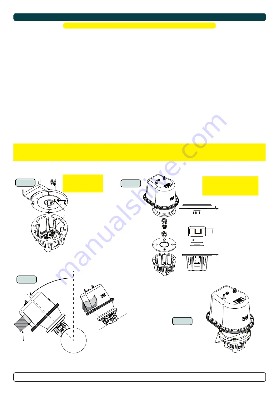
Motor Installation
1. If required remove the adapter plate from the motor bracket
2. Insert the lower part of the flexible coupling and tighten the set screw. Measure the height of the upper flexible coupling on the motor shaft.
3. Calculate and insert the lower flexible coupling on the gear leg at the correct height as per graphic and insert the red “plastic ring” in the lower
part.
Example:
height A = 24,54mm.
height B = 24,54mm + 1mm = 25,54mm.
The correct placement of the lower flexible coupling unit should be 25,54mm measured from the top surface of the motor bracket to the
bottom inner surface of the lower flexible coupling.
(NB: The extra 1mm is added to eliminate the risk of compression to the rubber
element between the two couplings.)
4. Fasten the coupling set screw to the lower flexible coupling and apply blue Loctite.
(NB: Ensure the axle key and key-way in the flexible coupling
are aligned.)
5. Install the motor onto the motor bracket ensuring the couplings are engaged together correctly (top and bottom).
(NB: The motor can be placed
in all directions on the motor bracket. However, ensure the cable terminals are accessible for electrical installation later.)
6. If you are installing the motor at an angle of more than 30º off vertical, the motor will require separate/ additional support.
(NB: Do not position
supports on the motors top cap.)
7. Fasten the bolts holding the motor to the motor bracket with the above torque.
8. Check the drive shafts are engaged by rotating the propeller.
(NB: Rotating the propellers can be hard due to the gear reduction and the motor,
however the propeller must be able to rotate via hand power.)
MC_0026
!
Please refer to the graphic for special considerations relating to your model
!
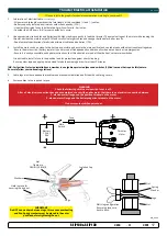
IMPORTANT
The thruster motor assembly must be protected using suitable covering to avoid dust/debris ingress from fabrication/maintenance/shipbuilding
operations. On completion of operations, the cover must be removed before operating the thruster.
MG_0072
a mm
b = a+1 mm
17mm
IMPORTANT!
The rubber/plastic element must
be in its correct position, fully
inserted but not compressed.
1
6
2 - 5
7
FASTEN
(33 Nm)
(24 lb/ft)
Motor support
> 30°
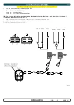
Holding Key
IMPORTANT
Ensure the holding key
and coupling are
aligned when fitted


