


20
6770
2
2021
-
PJC421 & PJC422
PHC-3
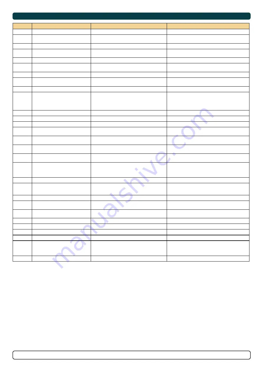
Fault Codes
MC_0117
Fault Code
Description
Cause
Action
10515.0.51
PHC DOUT 6 - Current High
Digital Output 6 current higher than 4.0A
-Check wires and connections for short circuit
10516.0.13
PHC DOUT 3 - Open Circuit
Digital Output 3 is confi gured as crossover and output is open
circuit
"-Check for open circuit, power consumption < 5.0 Watt
-Output confi gured wrong, parameter 0503"
10516.0.51
PHC DOUT 3 - Current High
Digital Output 3 current higher than 4.0A
-Check wires and connections for short circuit
10517.0.13
PHC DOUT 2 - Open Circuit
Digital Output 2 is confi gured as crossover and output is open
circuit
"-Check for open circuit, power consumption < 5.0 Watt
-Output confi gured wrong, parameter 0502"
10517.0.51
PHC DOUT 2 - Current High
Digital Output 2 current higher than 4.0A
-Check wires and connections for short circuit
10518.0.13
PHC DOUT 1 - Open Circuit
Digital Output 1 is confi gured as crossover and output is open
circuit
"-Check for open circuit, power consumption < 5.0 Watt
-Output confi gured wrong, parameter 0501"
10518.0.51
PHC DOUT 1 - Current High
Digital Output 1 current higher than 4.0A
-Check wires and connections for short circuit
10519.0.13
PHC DOUT 4 - Open Circuit
Digital Output 4 is confi gured as crossover and output is open
circuit
"-Check for open circuit, power consumption < 5.0 Watt
-Output confi gured wrong, parameter 0504"
10519.0.51
PHC DOUT 4 - Current High
Digital Output 4 current higher than 4.0A
-Check wires and connections for short circuit
10520.0.51
PHC ECI PUMP POWER FEED - Current High
ECI cooling pump power current higher than 8.0A
"-Check that the pump housing and impeller are clean, free from
debris or marine growth, and that the impeller can rotate easily.
-Check pump cable for damage and short circuits
-Make sure the connector on the cooling pump is correct inserted.
-Replace cooling pump"
10521.0.51
PHC Bow Thruster Power - Current High
Bow thruster PVG feed current higher than 3.0A
-Check PVG wires and connections for short circuit
10522.0.51
PHC Stern Thruster Power - Current High
Stern thruster PVG feed current higher than 3.0A
-Check PVG wires and connections for short circuit
10523.0.51
PHC Thruster Power - Current High
Bow or Stern PVG feed current higher than 3.3A
Check all bow and stern PVG signal wires for short circuits
10524.0.51
PHC ECI Cooling Pump - Current High
ECI cooling pump current higher than 13.0A
"-Check ECI cooling pump cable for damage and short circuits
-Replace ECI cooling pump"
10524.0.53
PHC ECI Cooling Pump - Overvoltage
ECI cooling pump overvoltage, voltage higher than 33.0V
"-Check PHC-3 input voltage is below 33.0V
-Replace ECI cooling pump"
10524.0.54
PHC ECI Cooling Pump - Undervoltage
ECI cooling pump under voltage, voltage is lower than 18.0V
"-Check PHC-3 input voltage is higher than 18.0V
-Replace ECI cooling pump"
10524.0.55
PHC ECI Cooling Pump - Overtemp
ECI cooling pump temperature higher than 100°C (212°F)
"-Check ECI cooling pump for damages
-Replace ECI cooling pump"
10524.0.100
PHC ECI Cooling Pump - No Communication
No communication with ECI cooling pump
"-Check if ECI pump is connected
-Check wires to ECI pump for open circuits
-Check power supply cooling pump
-Wrong cooling pump confi gured, parameter 0301"
10524.0.205
PHC ECI Cooling Pump - HW FAULT
ECI cooling pump hardware fault
-Replace ECI cooling pump
10526.0.0
PHC ECI Cooling Pump Blocked - -
ECI cooling pump is blocked
"-Reset fault and if fault reappears, cooling pump need service or
replacement.
-Check pump inlet for obstacles"
10527.1.0
PHC VFD Not Ready Instance 1 -
VFD not ready
-VFD external run enable/power available signal is lost.
10528.1.10
PHC VFD ABB Parameter Instance 1 Level Low
ABB ACS550 parameter values 2001 or 2002 cannot be a
negative value.
-Check ABB ACS550 parameter 2001 and 2002.
10529.0.19
PHC ECI Cooling Pump Speed - Under Limit
ECI pump motor speed under limit. Motor speed is below 100
rpm, or not getting minimum 750 rpm with in 3 seconds.
"-Check hose for dirt
-Check pump inlet for obstacles"
10530.0.201
PHC PTO ENGINE INSTANCE - INIT FAIL
Parameter 1011-PTO ENGINE INSTANCE is not defi ned
-Set parameter 1011-PTO ENGINE INSTANCE
36000.1.24
ABB ACS550 Instance 1 Fault
ABB ACS550 fault
Se ABB ACS550 drive for more details
36002.1.24
VACON Instance 1 Fault
VACON VFD Fault
Se VACON drive for more details
36003.1.24
ABB ACS580 Instance 1 Fault
ABB ACS580 fault
Se ABB ACS580 drive for more details
36100.1.100
VFD Instance 1 No Communication
Lost communication with VFD
"-VFD not powered up
-VFD communication cable not connected or incorrectly wired
-On the VFD make sure the RS485 BUS TERMINATION is in ON
position"
36103.1.0
VFD IN LOCAL Instance 1 -
VFD in local mode
-Switch VFD to remote mode
Summary of Contents for PJC421
Page 43: ...43 6770 2 2021 PJC421 PJC422 6 5 94 5 112 4 74 0 74 0 10 4x 4x 3 PJC421 PVREL...
Page 44: ...44 6770 2 2021 PJC421 PJC422 84 0 166 0 74 0 156 0 98 0 6 5 95 0 195 0 10 4x 6x 3 PJC422 PVREL...
Page 45: ...45 6770 2 2021 PJC421 PJC422 4 x 5 5mm 17 25 79 0 78 5 44 0 74 0 PJC421 LF90 PJC422 LF90...
Page 46: ...46 6770 2 2021 PJC421 PJC422 4x 5 5mm 70 0 79 2 79 2 39 6 39 6 PJC421 LE90 PJC422 LE90...
Page 47: ...47 6770 2 2021 PJC421 PJC422 74 0 47 0 79 2 79 2 2 6 16 1 PJC421 LF90X PJC422 LF90X...
Page 50: ...50 6770 2 2021 PJC421 PJC422 MC_0037 Notes...