


6
SRV(P)130_170_210
1.1.8 - 2017
TYPE SRV: Thruster with one speed
TYPE SRVP: Thruster with speed control
Motor:
Custom made reversible DC-motor.
Gearhouse:
Seawater resistant bronze. Ballbearing at
propellershaft and combination of ballbearing and slide
bearing at driveshaft.
Motor bracket:
Seawater resistant brass,
galvanicly insulated from motor
Tunnel:
Cross spun with rowing G.R.P tunnel
Propeller:
5 blade skew "Q"-propeller,
fibreglass reinforced composite.
Batteries:
Minimum recommended battery capacity
(cold crank capacity by DIN/SAE standard)
See table.
Max. use:
S2 = 3 min. or appr. 7-10% within a limited time frame.
(The actual duty time will vary - depending on
ventilation level, depth of thruster and actual
delivered voltage to thruster)
Safety:
Electronic time-delay device protects against sudden
change of drive direction. Electric thermal cut-off switch
in electromotor protects against over heating (auto reset
when electro motor cools down).
Flexible coupling between electro-motor and driveshaft
protects electromotor and gearsystem if propeller gets
jammed.
After a preset time in the panel(depending on panel
model), the panel will turn off, and the thruster will
retract.
The thruster will automatically retract when the panel is
turned off (manual or automatic)
Integrated microprocessor monitors solenoids,
reducing wear and risk of solenoid lock-in. Auto-stop of
thruster in case of accidental solenoid lock-in.
Technical specifications
EN
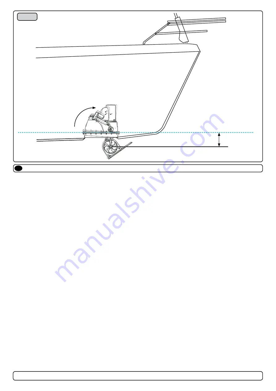
Fig. 1
Min. 250mm
WATERLINE
1
1
2
2
3
3
4
4
5
5
6
6
A
A
B
B
C
C
D
D
olekr
14.01.2015
Designed by
Checked by
Approved by
Date
1 / 1
Edition
Sheet
Date
Present issues:
1. Aproximately 5mm of the tunnel end covers have been cut, due to
adjustments. This causes incorrect angel and alignment.
2. Actuator support brackets have been moved to adjust. This also
causes incorrect angel and alignment.
Actions to be done:
3. Place and mould in an wedge between the upper and lower flanges
to adjust to correct angel and alignment.
4. Replace retract mechanism (without engine.)
1
1
2
2
3
3
4
4
5
5
6
6
A
A
B
B
C
C
D
D
olekr
14.01.2015
Designed by
Checked by
Approved by
Date
1 / 1
Edition
Sheet
Date
Present issues:
1. Aproximately 5mm of the tunnel end covers ha
ve been cut, due to
adjustments. This causes incorrect angel and alig
nment.
2. Actuator support brackets have been moved to
adjust. This also
causes incorrect angel and alignment.
Actions to be done:
3. Place and mould in an wedge between the upp
er and lower flanges
to adjust to correct angel and alignment.
4. Replace retract mechanism (without engine.)


