SLEIPNER MOTOR AS SRL 130/250 T Installation & User Manual Download Page 28

28

SRV(P)130_170_210


1.1.8 - 2017

How to use a bowthruster

1.  Turn main power switch for the bow thruster on. (Always turn off 


  the main power switch when not on board.) A Side-Power Automatic  

  Main Switch will turn on/off when the panel is turned on/off.

2.  Please take some time to exercise thruster usage in open water 

  to avoid damages to your boat.
3.  Turn the control panel on by pushing both “ON” buttons on the  

  original Side-Power panel simultaneously.
4.  Move the joystick in the direction you wish the bow  

  to move. Other controls like foot switches or toggle-switches on  

  the throttle can be used. These are connected to the S-link control     

  system by a S-link interface (Refer to schematics in interface manual  

  for installation)
5.  Depending on the sideways speed of the bow, you must  

  disengage the control device shortly before the bow is in the  

  desired direction, as the boat will continue to move after stopping  

  the bow thruster. 

How to use a single stern thruster

  Some boats might however have installed a single stern thruster  

  because of space limitation in the bow. In this case the stern  

  thruster is used in the same way as a single bow thruster or moving  

  the boat’s stern.

How to use a bow and stern thruster combined 

  The combination of a bow and stern thruster offers total 


  manoeuvrability to the boat and the opportunity to move the bow  

  and the stern separately from each other. This enables you to  

  move the boat sideways in both directions and to turn the boat  

  around its own axis staying at the same place. Refer to the PCJ  

  control panel manual for detailed instructions. 


•   Again, if in doubt, try in open water first!

SIDE-POWER


THRUSTER SYSTEMS

CONFIDENCE BY CONTROL

SIDE-POWER


THRUSTER SYSTEMS

User info, PJC-212 - 1/4

TECH INFO

USER INFO

PJC-212 Control panel

PJC-212 

Control panel with S-link

 CAN-bus connection

Product features 

•  For proportional thruster control with the new Power Controlled DC-thrusters
•  Finger tip control speed control with purpose designed joysticks
•  Hold 

-

 function for easy docking, runs thrusters at selected power

•  Back-lit 

LCD

 display with instant feedback

  - 

System status

  - 

Amount of thrust 

&

 direction of thrust

  - 

Thruster temperature/remaining run time 

  - 

Battery supply voltage to thrusters 

   - 

Monitoring of Automatic Mainswitch (informs if the fuse has blown 


or the manual override is activated)

•  Interactive multi-language menus
•  CAN-Bus communication with thrusters and accessories
•  Plug 

&

 play cables, waterproof and compact connectors

•  System setup via “wizard”
•  Diagnostics via panel/computer interface

•  Built-in audible alarm “buzzer”

•  Connector for external “buzzer”/loud audible alarms 
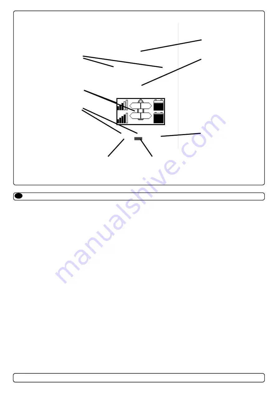
S-link

Speed control joystick for 

bow thuster

Speed control joystick for 

stern thuster

Holding function for auto-

running of bow and stern 

thrusters together in the 

direction of the arrows at  

selected power

Press “+” for more and 

“-” for less power.

Information display, see 

next page for details.

Press both “ON” buttons 

simultanously to activate 

control panel.

Press to change 

between day and 

night light

Press to access menu 

system and choose 

items in menus

Press to de-activate  

control panel or cancel or 

go back in menu system

How to use Side-Power thrusters

EN

Summary of Contents for SRL 130/250 T

Page 1: ...P O Box 519 N 1612 Fredrikstad Norway Tel 47 69 30 00 60 Fax 47 69 30 00 70 w w w s i d e p o w e r c o m sidepower sleipner no SRV L P 130 250 T SRV L P 170 250 TC SRV P 210 250 TC Installation User...

Page 2: ...surements thruster 3 Planning and important precautions 5 Technical specifications 6 Thruster installation Step by step installation 7 Fitting the electromotor 18 Electrical installation 19 150000 con...

Page 3: ...70 250 TC 60 9 SR P 210 250 TC 694 3 4 79 1 2 5 0 T 170TC 210TC 1 2 5 0 532 00 Max V angle for SR130T 170TC 210TC 3 SR P 130 250T SR P 170 250TC SR P 210 250TC 1 0 1 2012 Measurements thruster EN M ls...

Page 4: ...8 2017 Measurements thruster EN Lenght SRL P 130 250T 957mm SRL P 170 250TC 972mm 3 3 4 4 5 5 6 6 A B C D Designed by Elvira H Copyright All rights reserved SL E IP N E RM 957 300 238 430 523 93 250 4...

Page 5: ...b e e n c u t d u e t o a d j u s t m e n t s T h i s c a u s e s i n c o r r e c t a n g e l a n d a l i g n m e n t 2 A c t u a t o r s u p p o r t b r a c k e t s h a v e b e e n m o v e d t o a d...

Page 6: ...l retract The thruster will automatically retract when the panel is turned off manual or automatic Integrated microprocessor monitors solenoids reducing wear and risk of solenoid lock in Auto stop of...

Page 7: ...rements inside for the height and propeller depth under the waterline Find the most forward position where thruster unit will fit so center of the deployed thruster tunnel is at minimum 250mm under th...

Page 8: ...ster installation Positioning 3 Measure distances from upper flange edges down to hull as illustrated in Fig 4 Type the measurements on hull to easily transfer them to the SRF flange Important When me...

Page 9: ...the hatch use a suitable cutting tool with correct angle guide and gently cut out the hatch in accordance with Fig 8 b c Fig 8 Fig 8b Important Ensure when completing the cutting that the hatch does...

Page 10: ...filler is compatible with hull materials This is the boatbuilder installer full responsibility Fig 10 See appendix 2 Fig 10 10 Position the SRF flange with the upper thruster case resting on the SRF f...

Page 11: ...ht All rights reserved Part nr Size Scale Title Tole SLEIPNER MOTOR AS A2 N A 1 6 25 Weight A A B B C 52 5 348 5 BOW Hight control points SRV130 210 thrusters BOW 107 5 SRV130 170 240TC Control dimens...

Page 12: ...deepest where the hull and lower unit part meets Lamination moulding MUST be done by qualified personel Grind in this areas deepest where the hull and lower unit meets Layers of fiberglass cloth Appen...

Page 13: ...t in the aft end keeping the reference height in front until the hatch clears the hull Do not rotate the unit more than neccesary 2 3 degrees of rotation should be sufficient in most cases The closed...

Page 14: ...es from the water is absorbed Se alternative closing geometry that can be used Hatch Gap B B 1 10 C C 1 10 D E 1 2 F F 1 10 E F F 3 4 5 6 7 8 Designed by tore Copyright All rights reserved SLEIPNERMO...

Page 15: ...ustom made pin bolts to the tunnel rings The ends of the bolts must be sharp in order to create marks in the hatch The pin bolts must be in correct height so the hatch will fit in its inner position P...

Page 16: ...ith tunnel Bolts might be cutted depending on hull thickness Fig 18 Next process ist to fill the gap between hatch and hull edges Fig 18 18 Apply a layer of aluminium or duct tape on hatch opening edg...

Page 17: ...anual Fig 23 EN Step by step Thruster installation Upper thruster case and hatch fitting IMPORTANT Remember to remove the red installation part ref Fig 3 in step 2 IMPORTANT Any solutions regarding th...

Page 18: ...to 33Nm fig 11 4 Check the drive system by turning the propeller Make sure that the drive shaft is completly deployed i e 90 degrees to the hull It will be a little hard to turn because of the gear re...

Page 19: ...ntroller according to dia grams VISUAL WIRING DIAGRAM for SRV or SRVP version A main switch that can take the load without noticeable voltage drop must be installed in the main positive lead so the po...

Page 20: ...mption Less than 1 5 Watt in standby Fuse 12V 40 Amp Fuse 24V 40 Amp Minimum Voltage at B B for deployment 11 7 Volt for 12 Volt thruster 23 4 Volt for 24 Volt thruster Operating temperature 10 C to 6...

Page 21: ...The S link control system is powered by a dedicated power cable con nected to the system backbone as a normal spur cable The cable ends connect to battery pos and battery neg and the cable shield con...

Page 22: ...22 SRV P 130_170_210 1 1 8 2017 Technical wiring diagram SRVP models Visual wiring diagram SRVP models...

Page 23: ...elect Operation Mode thruster retracts Continous red light Motor overtemp Controller overtemp Controller no communication Motor relay failure Low battery voltage Position sensor failure No power to ac...

Page 24: ...very season always check that The propeller is securely fastened The bolts holding the electric motor to the motor bracket are fastened correctly The universal joint in the retract mechanism is lubric...

Page 25: ...rmation transfer on a single cable Proprietary Sleipner commands but built 100 on NMEA 2000 standard no Power cable spur Must be one in each system delivered in the length of 2 5m Part 6 1328 T connec...

Page 26: ...nning precautions Routing the Backbone Plan routing of the backbone so that lenght of spur cables will be kept at a minimum Avoid routing the S link cables close to equipment that might cause interfer...

Page 27: ...s PANEL OFF push OFF button thruster retracts For a detailed description of status and alarm messages shown please refer to the manual included with the control panel Status and alarms includes Overte...

Page 28: ...ow In this case the stern thruster is used in the same way as a single bow thruster or moving the boat s stern How to use a bow and stern thruster combined The combination of a bow and stern thruster...

Page 29: ...otor body and positive terminal on the motor and between the electromotor body and the negative A1 terminal on the motor The bolts holding the electromotor to its bracket are tightened correctly Check...

Page 30: ...ve system You must then immediately stop trying to run it and turn it off as running the electromotor for more than a few seconds without resistance from the propeller can cause serious damage to the...

Page 31: ...uired to turn the drive shaft by hand deploy the thruster as normal by turning the control panel on wait until the thruster stops in deployed position and turn the battery switch off Remove the fan co...

Page 32: ...nd of the purchase price Purchaser must submit a statement in writing from a professional boating equipment supplier that the installation instructions of the Installation and Operation Manual have be...

Page 33: ...33 SRV P 130_170_210 1 1 8 2017 Partslist SRV130 250T...

Page 34: ...34 SRV P 130_170_210 1 1 8 2017 Partslist SRV170 250TC...

Page 35: ...35 SRV P 130_170_210 1 1 8 2017...

Page 36: ...no The information given in the document was correct at the time it was published However Sleipner Motor AS can not accept liability for any inaccuracies or omissions it may contain Continuous produc...

Reviews: