background image

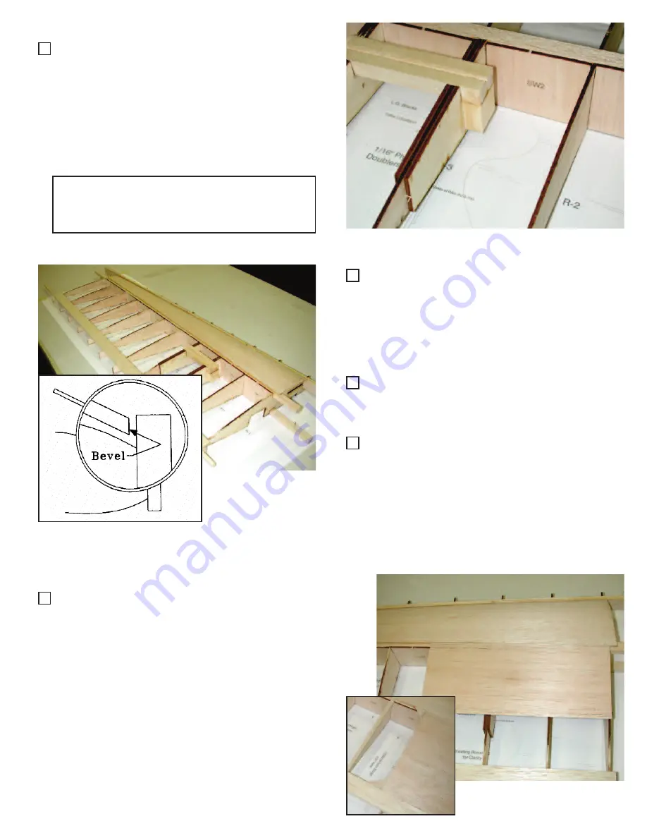
27. Fit the grooved landing gear block into the

notches in R3 and R4. It should have a 1/2”
overhang on the end with the hole. Insure
this block fits flush with the top edge of the
ribs. When satisfied, remove block and use
30 minute epoxy to glue in place along with
the  1/2”  x  7/8” x  1”  vertical  gear  block  as
shown in photo.

Taildragger Version:

The  gear  blocks  will  be  forward  of  the  main
spar.

28. Using  the  3/32”  tapered  leading  edge

sheets  made  previously  in  step  15,  bevel
the angle to match where the ribs meet the
leading  edge.  Check  for  proper  fit  -  there
should  be  no  gaps  between  the  sheeting
and the leading edge. Sand if necessary.

29. Pin or weight the trailing edge of the wing

to  the  building  surface.  The  wing  must
remain flat when sheeting the front portion.

30. Apply  thick  CA  to  the  tops  of  all  ribs.

Working  quickly,  align  the  front  of  the
sheeting  to  the  rear  of  the  leading  edge
piece and glue with thin CA. Once dry, roll
the sheeting to the rear down on top of the
spars  and  add  weight  to  hold  flat  against
the ribs. Glue the rear edge of the sheeting
to the top spar using thin CA. 

31. Using  the  3/32” x  4” x  24” sheet  provided,

cut  two  pieces  9-1/2” long.  Glue  these  in
place  over  R1  thru  R4,  keeping  one  end
flush with R1. Cut and fit a piece to fill into
the  gap  left  between  the  center  section
sheeting  and  the  trailing  edge  sheeting.
Glue in place. 

Option: 

If desired for looks, the rounded corners

shown on plan can be cut from scrap 3/32” sheet
and added.

9

Summary of Contents for Fantasy

Page 1: ... wing trainer kits available today Heavy duty wing spars and fuselage make for an aircraft that can withstand the mishaps that normally occur with a begining pilot Laser cutting and hand selected balsa allows us to keep the weight and building time to a minimum If you are an experienced builder the Fantasy can be built and ready to fly in the same amount of time as many ARFs For the sport flyer th...

Page 2: ... a particular process The laser does not cut through the wood it burns its way through As a result of this occasionally there will be scorching on the surface of the wood This is normal and is only a surface discoloration and does not affect the wood in any other way Similarly the laser settings are opti mized for wood density averages so occasionally due to variations even in individual sheets so...

Page 3: ... 1 Firewall 1 4 Wing Dowel 2 oz Fiberglass Wing Joining Material Elevator Connector Wire Landing Gear Straps 4 5 32 Wheel Collars 4 CA Hinges 18 Dubro Control Horns 1 pk Dubro Easy Connectors 2 1 4 Nylon Wing Mounting Bolts 2 Needed to complete kit Thin CA Glue Medium CA Glue Thick CA Glue We use Balsa USA Gold on our prototypes RC56 Canopy Glue 5 Minute Epoxy 30 Minute Epoxy Epoxy Brushes 2 rolls...

Page 4: ... when building The Taildragger version should not require any additional tail weight 1 Find vertical fin MS401 MS404 elevators MS403 horizontal stab MS405 and rud der MS402 parts 2 Over the plans join MS405 to the 1 4 x 3 x 24 balsa sheet with thin or medium CA 3 Join MS401 to MS404 so they align with the plans Use thin or medium CA 4 Remove above pieces from the plan and mark a center line on the...

Page 5: ...wire in place Let cure and remove from board 11 Trial fit all hinges to assure proper align ment Do no glue hinges at this time 12 Bevel leading dege of all control surfaces so they move at the proper deflections Sand to marked line and round all outside edges of the tail group Do not sand areas that will be inside the fuse and rudder tail blocks 13 Start the wing assembly by removing the balsa ri...

Page 6: ... dry and join the other 2 sheets the same way Lightly block sand both sides of the joined sheets in order to smooth out the glue line 16 Take the two 8 wide sheets from previous step and trim each sheet to 5 3 4 wide Make a mark 1 3 4 down from the upper left corner and 1 3 4 up from the bottom right corner With a 36 steel rule carefully join the two marks and cut along the line Set these sheets a...

Page 7: ... be removed later 19 Using thin CA reinforce the thin area of the tabs on the front of ribs R10 and R11 This will insure the tabs will stay on the ribs while you are building the wing 21 Carefully fit the top spar into all rib slots and glue Make sure that all ribs remain at 90 degrees from the building surface Note An easy way to insure the ribs are aligned and evenly spaces is to check them with...

Page 8: ...e piece and sand the trailing edge to match the taper of the ribs Make sure to leave the bottom part of the tab attached to rib This sets the correct washout for the wing 26 Locate grooved landing gear blocks 1 2 x 7 8 x 3 7 8 and drill a 5 32 hole at 90 degrees in the bottom of the landing gear block groove 3 8 from the end 25 Using thick CA glue a 3 32 x 1 x 30 sheet to the trailing edge of the ...

Page 9: ...ary 29 Pin or weight the trailing edge of the wing to the building surface The wing must remain flat when sheeting the front portion 30 Apply thick CA to the tops of all ribs Working quickly align the front of the sheeting to the rear of the leading edge piece and glue with thin CA Once dry roll the sheeting to the rear down on top of the spars and add weight to hold flat against the ribs Glue the...

Page 10: ... of R1 thru R11 Lightly sand any imperfec tions left in those areas 38 Turn wing upside down Place a 1 tall block under the trailing edge at R1 and a 1 2 block under the trailing edge at R11 this will maintain the correct washout You can also cut a block to fit under R6 to insure the trailing edge doesn t flex while sheeting the wing Pin the wing to these blocks and to the building surface 39 Tape...

Page 11: ...the two pieces of 3 8 x 1 x 36 tapered aileron stock Cut each in three pieces to the length shown on the plan for inner and outer trailing edge and aileron 46 Take the two 2 5 8 pieces and groove the fronts Also groove the wing trailing edge to accept the tubing on the aileron torque rod 47 Lay the two 2 5 8 pieces end to end and measure 1 2 from the center line in each direction At these points c...

Page 12: ...done on the elevator halves Cut the slots for hinges in the ailerons and wing trailing edge Install aileron hinges and aileron Do not glue hinges or torque rod until covering is completed 51 Glue two 1 tapered trailing edge pieces to the outboard end of the wing trailing edge with medium CA 52 Block sand aileron and trailing edge pieces to blend smoothly with wing sheeting Note To make sanding the...

Page 13: ...ecure one end of the fiber glass tape to the wing center section Wrap it tightly around the wing providing open ings for the aileron torque rods Brush with 30 minute epoxy insuring that all parts of the cloth are saturated You can also attach the cloth with thin CA Note If you use epoxy you can use a small amount of denatured alcohol to thin it and make it easier to spread 60 When epoxy or CA is c...

Page 14: ...s in FD1 You will use these slots for alignment of the bulkheads later Note Make sure you have a right and left side The ply doublers face inward when the sides are standing vertical 7 Locate F1 Firewall and align your engine mount with the scribed lines on firewall Drill holes and install motor mount as instructed by the mount manufacturer 8 Using the steering arm as a guide mark the location of ...

Page 15: ...down so make sure the firewall is facing the correct way 12 Place C1 on the plan and pin in place with the scribed lines facing down Align the left fuselage assembly with C1 and place B2 in the location shown on the plan Note If you are using the supplied flexible pushrods insure the 2 round holes in B2 are clos est to C1 If you are making control rods from dowels turn B2 so the rectangle cutout i...

Page 16: ...he fuselage easier 16 Wet the outside and bring the fuse side into alignment with the plan Glue with medium CA at the tail 17 Locate and glue with 5 min epoxy PW so that it fits flush with the top of the cut out for the horizontal stab This can be done while the fuselage is pinned to the building sur face or you can unpin the fuselage and turn it over as show in the photo 18 Using the 1 4 sq x 36 ...

Page 17: ...ce on the bottom of the fuselage at the very rear mark shape and sand to fit Glue in place for tail wheel mount 22 Once all pieces are glued and trimmed sand flush with sides Remove fuse from building surface 23 Locate the two 7 8 x 1 2 x 1 5 8 wing hold down blocks Bevel each block so it will fit flush with B2 and parallel with wing saddle 24 When satisfied with fit use 5 minute epoxy to glue blo...

Page 18: ...ll the wing only to 1 4 28 Using a 1 4 20 tap tap the wing blocks Figure 1 Note After tapping clean the treads and apply thin CA Allow plenty of time to cure and re tap This will give you good strong threads 29 Sand the balsa filler on the bottom of F1 so it is flush with the fuselage sides 30 Sheet the bottom of the fuselage from the wing saddle to F1 as shown in photo 31 Locate CS1 balsa strips ...

Page 19: ...16 balsa stringers as spacers center both pieces Mark loca tion and glue 35 Bevel bottom of 1A 1B assembly Center and glue TG backrest flush with bottom 36 Align the front of TG to the scribed line in C2 Adjust the length of TG to fit around C3 Glue in place with medium CA 37 Remove turtle formers 2 3 4 5 6 7A 7B from 1 8 ply sheet Glue 7A and 7B togeth er so they align with each other 19 ...

Page 20: ...he stringers to turtle 7 Note For a more finished look and increased strength you can also sheet the turtledeck with 1 16 balsa 41 Install the flexible pushrods for the steering and throttle cable at this time 42 Now you are ready to install the fuel tank Assemble fuel tank and set tank into the tank compartment Determine necessary foam padding to hold tank in the center so that it will be even wi...

Page 21: ... 1 4 sq x 36 stringer and cut to fit between B4 and B6 Align and sand so the stringers are flush with the top edge of B4 Glue stringers to B4 B5 and B6 with medium CA 46 Sand stringers flush with the curve in B4 thru B6 47 Cut 3 32 sheeting to fit over the cowl stringers and flush with the fuselage sides Bevel the edges of the 3 32 sheeting so they will fit flat on the fuselage sides Apply medium ...

Page 22: ...izontal stab on the fuse Sight from the rear and make certain the horizontal stab is parallel with the top of the wing This is important for straight flight Carefully sand the stab saddle so the horizontal stab sits level 52 Remove horizontal stab and align TS2 90 degrees on TS1 along the scribed line so they form a T shape 53 Place the spacer assembly on the stab saddle and center it at the front...

Page 23: ...tical and horizontal stab in place 55 Once the blocks are sanded to shape remove and discard the spacer The blocks should now have a taper that matches the stringer angle as shown in photo Sand the rear of the blocks to match the fuselage length 56 Remove the 1 8 ply triangles and servo plate from the laser cut sheet Assemble them as shown in the photo use medium CA This assembly can be glued to t...

Page 24: ...the aileron torque rod hole in order to secure it and keep it from wearing the balsa on the aileron 10 Install radio equipment where shown on the plan Be sure to follow the radio manufacturer s instructions Wrap the receiver and battery in 1 4 or 1 2 foam rubber to protect them from vibration We use Hitec 475BB standard ball bearing servos and standard Hitec 8 channel receiver in our prototype The...

Reviews: