background image

Page 78

December 2007

Rough Terrain Scissors 

Labels 

Section 5

No. Label Pictorial

Description

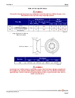
28

Skyjack Inc. 55 Campbell Road, Guelph, Ontario N1H 1B9 Canada

Max. incline

                  N

Max. manual force

Max. wind speed

    m/s

     kg

Wheel load

      bar

Lift pressure

System pressure

       bar

Platform height

      m

Drive height

      m

Machine weight

       kg

Voltage

    V

Capacity and maximum number of persons

    kg =   p equipment

Serial number

SJ

Model number

Made in Canada

TM

Serial Plate*

Product identification and specifications
*Serial plate will vary over different aerial platforms.

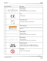
29

Hazard Identification

Refer to 

Section 1

: Safety Rules. Read and understand the

outlined risks associated with this work platform prior to
operation.

30

Emergency Main Power Disconnect

Main power disconnect lever

31

Ground Circuit Breaker

Push to reset ground circuit breaker.

32

Power Circuit Breaker

Push to reset power circuit breaker.

33

Generator Circuit Breaker (If Equipped)

Push to reset generator circuit breaker.

34

Connect Platform AC Supply

Connect AC power supply here for platform accessory outlet.

Summary of Contents for SJ8831 RT

Page 1: ...159149AC A August 2014 ROUGH TERRAIN SCISSORS MODELS SJ8831 RT SJ8841 RT SJ9241 RT SJ9250 RT OPERATING MANUAL CE...

Page 2: ...4 Coates Place Wetherill Park New South Wales 2164 Australia Tel 61 0 28786 3200 Fax 61 0 28786 3222 Skyjack Brasil Indaiatuba SP Brasil 13347 653 Tel 55 19 3936 0132 Alameda J piter 710 Loteamento Am...

Page 3: ...ates an imminently hazardous situation which if not avoided will result in death or serious injury WARNING WARNING indicates a potentially hazardous situation which if not avoided could result in deat...

Page 4: ...41 3 5 Component Identification 42 3 6 Component Identification Optional Equipment Attachments 44 3 7 Operator s Responsibility 45 3 8 Start Operation 46 3 9 Refueling Procedure 53 3 10 Loading Unloa...

Page 5: ...her warnings in this manual and on the aerial platform Compare the labels on the aerial platform with the labels found within this manual If any labels are damaged or missing replace them immediately...

Page 6: ...tect your eyes ears hands feet and body Any modifications from the original design are strictly forbidden without written permission from SKYJACK Electrocution Hazard This aerial platform is not elect...

Page 7: ...or operate elevated in windy or gusty conditions that exceed the limits specified in Section 4 Table 4 4 DO NOT increase the lateral surface area of the platform Increasing the area exposed to the win...

Page 8: ...issor arm assembly It is prohibited AVOID overhead obstructions Be aware of overhead obstructions or other possible hazards around aerial platform when lifting or driving AVOID crushing hazards Be awa...

Page 9: ...prohibited DO NOT exceed the rated capacity of the aerial platform DO NOT distribute load unevenly DO NOT operate if aerial platform is not working properly or if any parts are damaged or worn DO NOT...

Page 10: ...ground at all times during entering and exiting WARNING An operator should not use any aerial platform that does not appear to be working properly has been damaged or appears to have worn or missing p...

Page 11: ...ard could result in death or serious injury It is the responsibility of the operator to read completely understand and follow all instructions and warnings contained in this operating manual and on th...

Page 12: ...d the platform does not or only partially raises immediately lower the platform completely and ensure that the aerial platform is on a firm level surface 2 2 4 Load Sensing System This system is a saf...

Page 13: ...on when depressed disconnects power to the control circuit 2 2 6 Brake System The brake system is located on the main manifold in the hydraulic electrical compartment The brake must be manually diseng...

Page 14: ...ted on the hydraulic tank and is accessed through a hole in the hydraulic electrical compartment door 2 1 Figure 2 6 Emergency Lowering System 1 Emergency Lowering Pushbutton 2 Emergency Lowering Valv...

Page 15: ...ton when depressed disconnects power to control circuit and shuts engine off The red colored light indicates upper control availability and overload status When the light is continuously illuminated u...

Page 16: ...ermine that all labels are in place and are legible 2 3 2 Electrical Maintaining the electrical components is essential to good performance and service life of the aerial platform Inspect the followin...

Page 17: ...oper fluid levels or damaged cables and connections can result in component damage and hazardous conditions WARNING Explosion hazard Keep flames and sparks away Do not smoke near batteries WARNING Bat...

Page 18: ...fasteners Load Tilt Sensor Ensure load tilt sensor is properly secured and there is no visible damage Hydraulic Tank Model 92xx Ensure hydraulic filler cap is secure Ensure tank shows no visible damag...

Page 19: ...is fully lowered and then visually inspect the sight gauge located on the side of the hydraulic oil tank The hydraulic oil level should be at or slightly above the top mark of the sight glass Fuel Tan...

Page 20: ...muffler and exhaust system are properly secured with no evidence of damage Engine Tray Ensure there are no loose or missing parts and no visible damage to the engine tray Ensure that both tray securin...

Page 21: ...are no fuel leaks DANGER Engine fuels are combustible Inspect the aerial platform in an open well ventilated area away from heaters sparks and flames Always have an approved fire extinguisher within...

Page 22: ...cured Ensure gate is in good working order Lanyard Attachment Anchors Ensure attachment rings are secure and have no visible damage AC Outlet on Platform Ensure outlet has no visible damage and free f...

Page 23: ...tenance support is properly secured and shows no visible damage Scissor Assembly Ensure scissor assembly shows no visible damage and no signs of deformation in weldments Ensure all pins are properly s...

Page 24: ...e Refer to Table 4 6 for wheel tire specifications WARNING Intermixing tires of different types or using tires of types other than those originally supplied with this equipment can adversely affect st...

Page 25: ...ldment Manual Storage Box Ladder Drive Axle Ladder Ensure there are no loose or missing parts and there is no visible damage Outriggers If Equipped Ensure there are no loose or missing parts and there...

Page 26: ...stand Section 3 8 Start Operation 2 4 1 Platform Control Console 1 Turn main power disconnect switch to on position 2 On engine control console select off on start switch to on position 3 On base cont...

Page 27: ...15 to 20 seconds 11 Depress and hold engine start pushbutton to start the engine Test Emergency Stop 1 Push in emergency stop button Result Engine should shut down and aerial platform functions shoul...

Page 28: ...nsure path of intended motion is clear 3 Select off lift drive key switch to drive position 4 Without activating enable trigger switch attempt to drive and steer the aerial platform Result Drive and s...

Page 29: ...trigger switch only Result Aerial platform should come to an instant and abrupt stop Test Speed Limit WARNING Be aware of overhead obstructions or other possible hazards around the aerial platform whe...

Page 30: ...latform to about 5 meter refer to Section 3 8 8 or Section 3 8 9 Result Each extension platform should extend 2 Retract each extension platform fully Result Each extension platform should fully retrac...

Page 31: ...unctions should not operate 2 Pull out emergency stop button and restart engine Test Base Lift Enable 1 On base control console select and hold lower neutral raise switch to raise position without sel...

Page 32: ...nt pull out and hold emergency lowering valve to fully lower the platform Result Platform should fully lower 4 To restore normal operation depress and turn holding valve manual override knobs clockwis...

Page 33: ...at stowed position fully retract all outriggers using auto level Result All four outriggers will retract until they are in the stowed up position WARNING Ensure that there are no personnel or obstruct...

Page 34: ...Outrigger partially extended attempt to lift the platform Result Lift function will not operate With Right Front Outrigger partially extended attempt to lift the platform Result Lift function will not...

Page 35: ...wed position Extend each outrigger until it raises the tires up approximately 2 Retract the Left Rear Outrigger until the weight is resting on the corresponding tire Extend the Right Front Outrigger u...

Page 36: ...Do not stop the towing vehicle rapidly Do not pull aerial platform down an incline 2 5 1 To Release the Brake Manually WARNING Do not manually disengage brake if the aerial platform is on an incline W...

Page 37: ...latform base or on top of fuel cabinet 4 On the hydraulic compartment pull out and hold emergency lowering valve item 2 to lower platform 5 To restore normal operation depress and turn holding valve o...

Page 38: ...Page 38 December 2007 Rough Terrain Scissors Notes...

Page 39: ...alified person 3 1 2 Operator s Responsibility for Maintenance WARNING Maintenance must be performed by trained and competent personnel who are familiar with mechanical procedures Death or serious inj...

Page 40: ...ection 3 Operation SKYJACK Model 8841 Aerial Platform Platform Control Console Entry Gate Base Main Platform Lifting Mechanism Hydraulic Electrical Compartment Extension Platform Maintenance Support 3...

Page 41: ...sed disc brake A roll out tray at the front of the base supports an engine coupled with a two section hydraulic pump providing power to the hydraulic system An engine control console is also located a...

Page 42: ...maintenance support push lock lever rearward and the maintenance support will drop Refer to Section 3 12 for procedure on how to use and store the maintenance support Figure 3 1 Maintenance Support W...

Page 43: ...erial platform check the guardrail system for loose or missing locking pins The guardrail system must be upright and all pins must be locked in place Death or serious injury could result if the guardr...

Page 44: ...rigger Enable Switch This outrigger enable switch when in the extend or retract position activates the functions on the auto level switch and the outrigger extend retract switches 5 Leveling Indicator...

Page 45: ...t into service IMPORTANT The operator must understand and follow the step by step instructions to test all aerial platform functions The operator should make a copy of the Operator s Checklist see Tab...

Page 46: ...ly has been damaged or appears to have worn or missing parts has alterations or modifications not approved by the manufacturer has safety devices which have been altered or disabled has been tagged or...

Page 47: ...tion can be reactivated 3 8 3 To Activate Platform Control Console 1 Turn main power disconnect switch to on position 2 On engine control console select off on start switch to on position 3 On base co...

Page 48: ...wering function can be reactivated NOTE If the tilt alarm sounds and the platform does not or only partially raises immediately lower the platform completely and ensure that the aerial platform is on...

Page 49: ...ending or descending grades traveling on rough terrain or when loading or unloading aerial platform To activate high torque select low high speed range switch to low speed high torque position WARNING...

Page 50: ...not in use pull the plungers item 3 on the push bar and retract it then rotate it back to its resting position and lock it into place with the locking pins item 2 3 8 9 To Extend or Retract Powered Ex...

Page 51: ...lly retracted Flashing Rapidly The outriggers are extending or retracting Flashing Not all outrigger legs have firm ground contact or aerial platform is not level On The outriggers are extended and th...

Page 52: ...NOTE Activating any lift or outrigger functions changing the key switch setting activating the emergency stop or an engine stall will turn off the generator The platform may be lowered during generato...

Page 53: ...NG Do not smoke in an area where aerial platforms are stored or refueled 3 9 1 Regular Fuel Diesel 1 Ensure engine and all systems are turned off and emergency stop buttons are depressed 2 Open fuel c...

Page 54: ...nloaded 3 10 1 Lifting WARNING Only qualified rigger shall perform lifting When it is necessary to lift the aerial platform the following conditions must be met The platform must be fully lowered The...

Page 55: ...Models 92xx that are equipped with designated lifting pockets See Figure 3 10 3 10 2 Driving Before driving the aerial platform Ramp or dock capacity must be sufficient to withstand maximum aerial pl...

Page 56: ...sion platforms are fully retracted 2 Turn main power disconnect switch to off position WARNING Ensure that you maintain three points of contact when using the ladder to mount dismount platform 3 Use t...

Page 57: ...nsion front and rear 5 Swing the right side guardrail up and lock it in place by inserting all locking pins 6 Swing the left side guardrail up and lock it in place by inserting all locking pins 7 Swin...

Page 58: ...Maintenance Support To Deploy the Maintenance Support 1 Remove all material from platform 2 Raise platform until there is adequate clearance to swing down maintenance support item 1 3 Push latch leve...

Page 59: ...owering warning system Manual brake release Maximum drive height Full Height Full Height Full Height 7 9 m Operator horn Overload sensing system Platform control console Rollout engine tray Scissor gu...

Page 60: ..._ Serial Number __________________ This decal is located on the scissor assembly It must be completed after an annual inspection has been completed Do not use the aerial platform if an inspection has...

Page 61: ...ative Engine Oil Engine Oil Capacity Liters Coolant Type Coolant Capacity Liters Sound Pressure Level ISO 3744 Guaranteed MaximumSound Power Level ISO 4871 140AF CE 1 7 m x 3 5 m 1 85 m x 4 39 m Stand...

Page 62: ...2 5 x 4 5 1 5 x 1 5 9250 Two Extension Platform 681 kg 5 227 kg 2 227 kg 2 12 5 m s 2 5 x 4 5 1 5 x 1 5 141AD CE NOTE Tilt Cutout Setting Outriggers Degrees Maximum Wind Speed Tilt Cutout Setting Degr...

Page 63: ...ace directly underneath it The structure of the operating surface beams etc must be able to withstand more than the indicated values above The LCP or OUP that an individual surface can withstand varie...

Page 64: ...Locally Concentrated Pressure LCP Overall Uniform Pressure OUP Foot Print Area Length x Width r2 Base Area Length x Width LCP Weight of Aerial Platform Capacity Foot Print Area x 4 Tires OUP Weight of...

Page 65: ...ailable Usage S S S S 6F 10 N A O 6F Foam 10 N A Tire Size Fill Specification Fill Type Ply Rating Pressure Factory kPa FULL SIZE Backspace Outboard Inboard SECTION A A A A Rim Backspace Diagram 8831...

Page 66: ...mity with the following directives Machinery Directive 2006 42 EC Notified body is EC type Examination Certificate No Directive 2004 108 EC Testing Laboratory The Technical Construction File is mainta...

Page 67: ...tment Test Horn A Engine Control Console A Test Driving A Radiator A Test Brake A Muffler and Exhaust A Test Speed Limit A Engine Tray A Test Lowering Warning A Hydraulic Pump A Test Powerdeck Enable...

Page 68: ...l Models Except 9250 Wheel Tire Assembly Electrical Panel PASS Visual and Daily Maintenance Inspections Manifolds OPERATOR S CHECKLIST Each item shall be inspected using the appropriate section of the...

Page 69: ...els 5 Label Legend Safety Red Safety Red indicates DANGER Safety Orange Safety Orange indicates WARNING Safety Yellow Safety Yellow indicates CAUTION Safety Green Safety Green indicates emergency lowe...

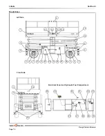
Page 70: ...cember 2007 Rough Terrain Scissors Labels Section 5 Models 8831 8841 Right Side Front Side Hydraulic Fuel Compartment Cylinder 1 2 4 3 5 6 7 8 10 11 5 6 7 2 4 3 12 13 2 14 15 16 17 18 19 14 1 2 20 21...

Page 71: ...2007 Page 71 Section 5 Labels Models 8831 8841 147197AA ZZ TM Left Side Back Side Electrical Panel and Hydraulic Fuel Compartment 1 4 3 5 6 7 10 8 5 6 7 4 3 12 13 2 14 15 16 17 26 19 14 1 2 25 28 27...

Page 72: ...ain Scissors Labels Section 5 Model 92xx Left Side Front Side Electrical Panel and Hydraulic Fuel Compartment 147197AA ZZ TM 1 4 3 5 6 7 5 6 7 4 3 12 13 2 14 15 16 17 26 10 27 37 37 8 19 14 1 2 30 31...

Page 73: ...gh Terrain Scissors December 2007 Page 73 Section 5 Labels Model 92xx Right Side Back Side Fuel Compartment Cylinder 1 4 3 5 6 7 5 6 7 4 3 12 13 2 14 15 16 17 11 10 37 37 8 2 18 19 1 28 25 23 24 22 29...

Page 74: ...Caution stripe 3 Keep Clear Keep clear Stay away from aerial platform when in operation 4 Crushing Hazard Danger Crushing hazard 5 Wheel Load Indicates rated wheel load Wheel load will vary with each...

Page 75: ...power level 11 Annual Inspection Ensure that work platform has received annual inspection prior to operation 12 Model Number Product Identifier Model number will vary may not be as shown 13 Model Num...

Page 76: ...2 Raise platform until there is adequate clearance to swing down maintenance support 3 Swing maintenance support down from storage bracket into a vertical position Lower platform until the bottom end...

Page 77: ...limit switches or other safety devices 26 Manual Storage Box Indicates location of operating manual 27 Emergency Lowering Procedure Refer to operating manual 1 Turn main power disconnect switch to of...

Page 78: ...a TM Serial Plate Product identification and specifications Serial plate will vary over different aerial platforms 29 Hazard Identification Refer to Section 1 Safety Rules Read and understand the outl...

Page 79: ...t aerial platform from rolling 2 Turn main power disconnect switch to off position 3 Locate brake valve pump and lever 4 Attach lever and push in black knob 5 Pump lever 1 3 times Brake is now release...

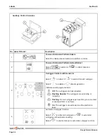
Page 80: ...in operation 2 Crushing Hazard Danger crushing hazard 3 Warning Do Not Alter Do not alter or disable limit switches or other safety devices 4 Engine Control Select to start run or stop engine Select...

Page 81: ...Railing Pins Horizontal If Equipped WARNING Falling Hazard Make sure hinged railing is pinned properly 3 Falling Hazard Railing Pins Vertical If Equipped WARNING Falling Hazard Make sure hinged raili...

Page 82: ...rive reverse 2 Low High Speed Range Select for low speed high torque or high speed low torque 3 Low High Throttle Select low or high engine speeds 4 Power On Overload Indicator Continuous illumination...

Page 83: ...r drive mode 7 Emergency Stop Push to disable controls 8 Lift Enable Select to enable lift mode 9 Start Engine Select to start engine 10 Glow Plug Select to activate glow plugs 11 Horn Select to sound...

Page 84: ...tend for each outrigger Select to enable or disable generator Indicates leveling system status Off The outriggers are fully retracted Flashing Rapidly The outriggers are extending or retracting Flashi...

Page 85: ...Rough Terrain Scissors December 2007 Page 85 Notes...

Page 86: ...Page 86 December 2007 Rough Terrain Scissors Notes...

Page 87: ......

Page 88: ...www skyjack com elig lift l sninger av folk som bryr seg...

Reviews: