DA 1700 dual actuator
66
Technical User Guide
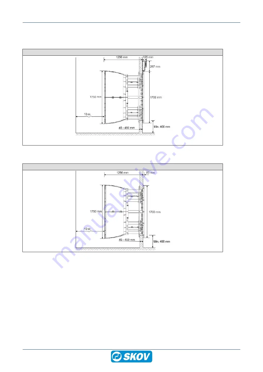
8 Dimensioned sketch
8.1 Wall fan with LPC motor controller
DA 1700 with LPC motor controller
(B)
(C)
(D)
(E)
(A)
8.2 Wall fan
DA 1700 without LPC motor controller
Page 1: ...04420 2021 08 17 English For other language variants of this document we refer to Espa ol Para otras variantes del idioma de este documento visite Fran ais Pour les versions dans d autres langues de c...
Page 2: ...manual may be reproduced in any manner whatsoever without the expressed written permission of SKOV A S in each case All reasonable efforts have been made to ensure the accuracy of the information cont...
Page 3: ...ing the motor in the fan housing 26 3 15 Mounting top motor suspension 26 3 16 Cabling from motor and actuator 27 3 17 Foaming and pointing of the outside 28 3 18 Pointing of the inside 29 3 19 Mounti...
Page 4: ...plan 52 4 10 2 2 Circuit diagram 52 4 10 3 DA 1700 LPC 3x400 V 53 4 10 3 1 Cable plan 53 4 10 3 2 Terminals in LPC 3 x 400 V fan 53 4 10 3 3 Dual actuator control box LPC 54 4 10 3 4 Circuit diagram...
Page 5: ...low energy consumption and one version focused on maximizing air output DA 1700 dual actuator is characterized by having a particularly tightly closed shutter which prevents unwanted air movement when...
Page 6: ...s 1 pcs DA 1700 lifting kit and mounting parts are supplied For every 101 200 pcs 2 pcs DA 1700 lifting kit and mounting parts etc are supplied The lifting kit and mounting parts consist of DA 1700 li...
Page 7: ...as with particularly strong wind conditions to ensure an optimal climate for the animals Note that the dual actuator solution has a higher current consumption com pared to the standard shutter motor S...
Page 8: ...is sagging and has not maintained its round ness Delivered with mounting parts 1 per wall fan 560356 DA 1700 lifting kit and mounting parts ACT DA 1700 lifting kit is used for mounting the fan motor...
Page 9: ...as an unassembled unit incl brackets Used for DA 1700 wall fan if a large amount of dimming is required in the livestock house Light reduction factor 11 000 000 1 The light trap reduces the air output...
Page 10: ...fitting If the DA 1700 is installed in areas with risk of ice snow slide precautions must be made to avoid damage to the wall fan 3 1 Recommended tools A list of the recommended tools for mounting pur...
Page 11: ...DA 1700 dual actuator Technical User Guide 11 Item Description Foam gun Ladder Jigsaw Socket wrench set Water pump multi grip pliers Spirit level Try square 2 men...
Page 12: ...LPC motor controller B C D E A There must be a minimum of A space inside the live stock house for the wall fan There must be minimum of B of space including the wall thickness outside the livestock ho...
Page 13: ...n in mm Recommended measurements for individual mounting of wall fan A Minimum distance is 550 mm when mounting the LPC motor controller above wall fan Without LPC motor controller the distance can be...
Page 14: ...e given in mm Recommended measurements for individual mounting of wall fan A Minimum distance is 550 mm when mounting the LPC motor controller above wall fan Without LPC motor controller the distance...
Page 15: ...n in mm Recommended measurements for individual mounting of wall fan A Minimum distance is 550 mm when mounting the LPC motor controller above wall fan Without LPC motor controller the distance can be...
Page 16: ...DA 1700 dual actuator 16 Technical User Guide 3 4 Measure and saw out the holes Remember always to use a spirit level Drill 10 mm holes all the way through the wall Cut the holes...
Page 17: ...on the floor Press the front panels together in all 4 corners 3 6 Click and point the ventilation ducts together Silicone Point the side of the ventilation duct A B A B Click the 4 ventilation ducts t...
Page 18: ...lation duct on the front panel Assemble the front panel and the ventilation duct using 16 x M6x25 screws 32 x 6 washers 16 x bushings 6 10x11 6 16 x M6 self locking nuts Assemble the front panel and t...
Page 19: ...ar Mount the two shutters one at a time in the center pillar Mount top and bottom brackets on the center pillar using 2 x M6x50 screw 4 x 6 4 18x1 2 washers 2 x bushings 6 10x39 6 2 x M6 self locking...
Page 20: ...DA 1700 dual actuator 20 Technical User Guide Mount the shutter lock through the shutter and down around the center pillar Make sure that the shutter lock snaps into the center pillar...
Page 21: ...f locking nut Mount the dual actuator bracket for shutter in the inner most hole in the shutter using 2 x M6x20 screw 4 x 6 4 18x1 2 18 washers 2 x 10 5x25x3 washers 2 x 6 10x11 6 bushings 2 x M6 self...
Page 22: ...or on the dual actuator bracket for cen ter pillar using 2 x M6x30 screw 4 x 6 4 18x1 2 18 washers 2 x 6 10x22 bushings 2 x M6 self locking nut Mount the actuator on the dual actuator bracket for shut...
Page 23: ...r the wall fan in the hole use wedges at the bot tom Use the holes in the wall wall to mark out holes in the wall Mounting in a sandwich wall Drill 3 mm holes in the wall Mounting in brick or concrete...
Page 24: ...ine with each other Press the parts together Mount impeller on the motor shaft using 1 x M10x25 screw 1 x 10 5 45x3 washer It should be tightened at 55 Nm 3 12 Mounting bottom motor suspension Push th...
Page 25: ...3 13 Mounting lifting kit Mount the lifting kit on the ventilation duct using 2 x M6x80 screw 4 x 6 washers 2 x bushings 6 10x69 6 Make sure the blades do not touch the floor Mount the lifting kit on...
Page 26: ...ing beam Mount the top motor suspension brackets to the motor using 2 x M6x80 screws 4 x 6 washers 2 x bushings 6 10x69 6 2 x M6 self locking nuts For more details see section Mounting bottom motor su...
Page 27: ...tre mark 10 mm hole for the actuator cable at the top 13 mm hole for the fan motor cable at the bottom Mount the actuator cable on the center pillar using 2 x cable ties w fir tree mount 148x3 6 for 4...
Page 28: ...hane foam or similar Check how much the foam ex pands before foaming For pointing Sikaflex 111 Stick Seal Foam At round holes foam around the ventilation duct Foam At square holes foam in 4 places aro...
Page 29: ...Guide 29 3 18 Pointing of the inside SKOV A S recommends Sikaflex 111 Stick Seal S i l i c o n e Apply a sealing edge between the wall fan and the wall Silicone Apply a sealing next to all places whe...
Page 30: ...tical covers loosely with a screw in the middle hole Assemble the last covers without securing them to the wall If necessary use a saw to adjust the cover size Then mount all 4 covers on the wall with...
Page 31: ...31 3 20 Mounting the cone Ensure the tongue and groove at the base are in line Click the sides together Mount the assembled cone onto the ventilation duct us ing 8 x M6x25 screws 16 x 6 washers 8 x b...
Page 32: ...Mount the inside safety net using 2 x 4x30 screw 2 x 4 3 washers 2 x mounting straps for inside net in the 2 holes in the fan housing sides Secure the inside safety net in the 4 motor suspension brack...
Page 33: ...DA 1700 outside safety net has not been selected a safety guard must be established The requirements of the International Standard for Safety of machinery ISO 13857 shall be complied with Mount the o...
Page 34: ...rx 30 Make sure that the flaps can open and close when the storm protection is mounted 3 22 3 Mounting the storm protection wire for cone 8 5 m m Used if outside safety net is not used Drill a 5mm hol...
Page 35: ...crews for con crete wall and iron or B threaded rod for sandwich panel Screws for mounting are not included C Mount mounting fittings on ventilation duct with screw and washer for center pillar D Moun...
Page 36: ...50 screws 2 x 6 4 18x1 2 washers 1 x 6 10x11 6 bushings 1 x M6 self locking nut Mount threaded rod B in bracket A Tilt the threaded rod against the wall and shorten it to the correct length Mount 2 x...
Page 37: ...ical User Guide 37 3 22 6 Mounting insulation plate Mount the lock on the motor using 1 x 8x12 screw with inside hexagon 1 x 8 4 washers Mount the insulation cover at the end of the fan motor using 1...
Page 38: ...the electrical installations The focus should be on cable dimensions over load protections local transformers etc It is of outmost importance to take the fan specifications into account and at the sa...
Page 39: ...e In order to uphold protection classifications ensure ac cess of cables and cooling of the motor controller the distances to the surroundings of 150 mm must be ad hered to In order to prevent water f...
Page 40: ...terminals U V W PE 2 Connection terminals for braking resistor not used 3 Connector for optional module 4 Terminal block for programming interface 5 RJ12 programming connector 2 x slave 1 x master 6 3...
Page 41: ...DA 1700 dual actuator Technical User Guide 41 4 2 1 Terminals for power supply Power supply 3 x 400 V 3 x 230 V Power supply 1 x 230 V...
Page 42: ...ection from motor controller to fan motor 4 2 3 Signal terminals Not in use Not in use Ground Not in use Signal from controller Ground 10 0 V open 0 10 V GND Short circuit connection between terminal...
Page 43: ...LED flashes red The built in alarm monitoring stops the motor controller motor The alarm automatically resets if the error ceases and motor controller motor starts Reset the alarm if the maximum numb...
Page 44: ...tive at power failure To activate the fan at a power failure select Installation Manual installation cli mate Air outlet Tunnel outlet and after that Fans active at failure in the controller menu The...
Page 45: ...ns active at failure in the controller menu The default setting of MultiStep 4 to MultiStep 16 is set to be deactive To change this select the MultiStep which should be changed and select deactivate 2...
Page 46: ...LPC motor controller ON OFF motor controller Actuator extending open retracting closed Open close delay OFF 12 sec 12 sec 15 sec 4 sec ON OFF control signal Open Closed LPC motor controller ON OFF mo...
Page 47: ...upply D must be used and possibly E The A5 minus terminal is connected in parallel terminal A5 to A5 24V max 2 1 4 2 A 24V max 2 1 4 2 A The power supply must be connected to the controller using a mu...
Page 48: ...DA 1700 dual actuator 48 Technical User Guide 4 8 Jumper setting 1 6 6 0 LPC fan mode 1 and mode 6 ON OFF fan mode 0 and mode 6...
Page 49: ...k Color coding on wires are in accor dance with standard IEC 60757 Letter codes to identify colors used on drawings diagrams labelling etc BN Brown RD Red OG Orange YE Yellow GN Green BU Blue incl lig...
Page 50: ...ch 4 10 1 1 DA 1700 with LPC Example of terminal number For correct connection see the setup menu Show connections in the controller Actuator pcb Connection box Dual actuator Pay attention to the curr...
Page 51: ...mple of terminal number For correct connection see the setup menu Show connections in the controller Actuator pcb Connection box Power supply from terminals in the climate computer F6 Q1 Dual actuator...
Page 52: ...DA 1700 dual actuator Alarm 4 10 2 2 Circuit diagram Fan 3x400 V Example of terminal number For correct connection see the setup menu Show connections in the controller Actuator pcb Connection box LP...
Page 53: ...Technical User Guide 53 4 10 3 DA 1700 LPC 3x400 V 4 10 3 1 Cable plan DA 1700 dual actuator LPC motor controller Power supply isolator Controller Connection box 4 10 3 2 Terminals in LPC 3 x 400 V f...
Page 54: ...Fan 3x400 V Example of terminal number For correct connection see the setup menu Show connections in the controller Actuator pcb Connection box LPC motor controller Dual actuator Pay attention to the...
Page 55: ...Technical User Guide 55 4 10 4 DA 1700 ON OFF 3x400 V 4 10 4 1 Cable plan Connection box Power supply isolator Controller DA 1700 dual actuator ON OFF Wiring box 4 10 4 2 Terminals in ON OFF 3 x 400 V...
Page 56: ...uit diagram Fan 3x400 V Example of terminal number For correct connection see the setup menu Show connections in the controller Actuator pcb Connection box Dual actuator Pay attention to the current c...
Page 57: ...ashing from above 2 When washing the fan the fan blades must turn around Remember that fans do not stand high pressure cleaning 3 It is recommended that the fan run at 100 for at least one hour after...
Page 58: ...to the connection and circuit diagram Troubleshooting fan motor Fault symptom Status LED Error Solution Abnormal noise coming from fan Faulty mounting Check in accordance with the docu ment Retighten...
Page 59: ...ing to the motor Internal communication error Replace LPC motor controller Reduced performance Flashes red Supply voltage too low Measure the supply voltage Internal temperature of the LPC motor contr...
Page 60: ...nding on the output as the different frequencies with corresponding leakage currents will not be present at the same time 1 0 30 5 34 42 2 6 Pay attention to other leakage current sources in the house...
Page 61: ...at 10 Pa m3 kWh 36100 Specific energy at 10 Pa Watt 1000 m3 h 28 Testing body SKOV A S Environment Temperature operation C 40 to 40 Start temperature C 40 to 50 Storage temperature C 40 to 70 Ambient...
Page 62: ...ciency 36 0 VSD required Yes Year of production 2020 Name of manufacturer SKOV A S Item number 435369 Motor power input kW 2 310 Flow rate m3 s 10 3 Optimum pressure Pa 125 Revolutions per minute RPM...
Page 63: ...des pcs 3 Fan blade pitch 45 Fan output Revolutions rated cur rent per minute RPM 700 Air output at 0 Pa m3 h 59600 Air output at 10 Pa m3 h 58000 Air output at 20 Pa m3 h 56300 Air output at 30 Pa m3...
Page 64: ...g 34800 Impeller weight g 7500 7 2 1 ErP Ecodesign DA 1700 7 ACT 3x400 V Fan type DA 1700 7 ACT 3x400 V Ecodesign ErP 2015 40 Efficiency classification N 53 2 Efficiency 49 1 Measurement setup A Fan...
Page 65: ...A pcs 6 Number of actuators on DOL 278A X large 24V 10A pcs 7 Mechanical Cable length m 3 2 Running time unloaded at 24 V DC sec 12 Running time max load at 24 V DC sec 15 Torque N 300 Environment Tem...
Page 66: ...00 dual actuator 66 Technical User Guide 8 Dimensioned sketch 8 1 Wall fan with LPC motor controller DA 1700 with LPC motor controller B C D E A 8 2 Wall fan DA 1700 without LPC motor controller B C D...
Page 67: ...DA 1700 dual actuator Technical User Guide 67 8 3 LPC motor controller LPC motor controller 3x400 V 8 4 Light trap Light trap black brown out...
Page 68: ...604420 2021 08 17 en US Made in Denmark SKOV A S Hedelund 4 Glyng re DK 7870 Roslev Tel 45 72 17 55 55 www skov com E mail skov skov dk...