Quick Setup/Installation Guide for Lubrication Monitor Controller LMC 301
951-150-029-EN
13
5. Configuration by operator/local admin
General
There are two options for configuring the
controller:
o Configuration with PC software and USB
connection -see Chapter 6.1.
o The PC software application is designed for
Windows XP, Windows 7, and Windows 8
operating systems and is included as data
media with the controller. The software can
also be downloaded as freeware from the
SKF website. After installing the program,
data transfer occurs via the USB interface
in the controller.
o SKF recommends this procedure for initial
installations.
o Configuration of the system using the
display attached to the controller and the
menu keys - see Chapter 5.1.
o The complete configuration can be done
via the controller display and the associ-
ated menu keys.
5.1 Coniguration of the controller unit
with PC software
)
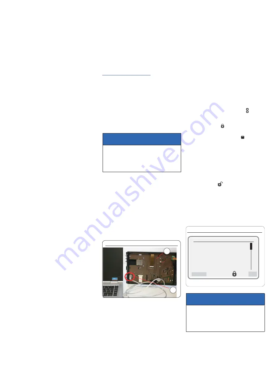
see Figure 15
• From the SKF homepage
http://www.skf.com/LMC301/
• Download software
LMC 301 PC Software
• Close all applications on the laptop.
• Open the file.".
)
After you enter the password, the LMC 301
software installs automatically. SKF recom-
mends not starting any other applications
during this period.
ATTENTION!
The USB cable may only be
connected to the USB port installed inside
the controller lid on the LMC 301.
- see Fig. 15.
Connect the USB cable, Fig. 15
2
1
• Install the controller unit (Chapter 4.3).
• Open the controller unit (Chapter 4.2).
• Connect the USB cable (
2
) from the laptop
on the inside of the controller lid (
1
) and
turn on the power supply.
• Start the LMC 301 software.
)
The description of the PC configuration is
included with the software.
• Configure according to the included de-
scription for configuration on the PC.
5.2 Coniguration of the controller unit via
the display on the controller unit
5.2.1 Status/overview
After switching on the supply voltage, the
Overview States
menu appears on the
display.
The current parameter settings and values
are displayed. This is done continuously and
automatically.
The parameters and settings can optionally be
accessed using the two arrow keys .
No entries can be made and the symbol
shows a closed lock
.
To change the configuration, select the
Menu
menu item using the control key .
This will take you to the
Main menu
.
Changes can be made within the main menu
only after entering the password. This is done
in the
Login settings
menu level.
When entering the password, there is a dif-
ferentiation between
Local Admin
(customer
access) and
Supervisor
(only service staff, no
customer access).
The open lock icon
indicates that the system
has been unlocked.
5.2.2 Main menu
Main menu, Fig. 16
Main menu
Login settings
User settings
Device settings
Pump 1 Timings
Information
Back
OK
ATTENTION!
The description of the main menu is based
on settings that the end customer can adjust.
(password level Set PW local admin)


