background image

TM

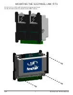
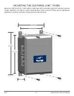
MOUNTING THE SJE PANEL LINK

™ 

RTU

5.5”W x 4.5”H x 3.5”D (with antenna at 90 degrees as shown)

Can be din rail mounted or panel mounted with 4 screws.

SJE

®                            

                                                                     7                                          SJE Panel Link

 RTU User Manual

Summary of Contents for Panel Link Light

Page 1: ...SJE PANEL LINK RTU WEB BASED CELLULAR REMOTE MONITORING CONTROL PANEL User Manual SJE Panel Link TM ...

Page 2: ... with National Electrical Code ANSI NFPA 70 so as to prevent moisture from entering or accumulating within the controller housing ELECTRICAL SHOCK HAZARD A qualified service person must install and service this product according to applicable codes and electrical schematics Disconnect power prior to servicing an equipment with the SJE Panel Link RTU EXPLOSION OR FIRE HAZARD Do not use this product...

Page 3: ...nting the Panel Dimensions and Mounting 12 Wiring Methods 13 System View 14 Wiring 15 SJE Panel Link Troubleshooting 16 Logging In 17 Access Levels 18 Viewing Searching for RTUs 19 Placing an RTU on the Map 21 User Setup 22 Dashboard 23 RTU Setup 24 Online Offline Trigger Alert Setup 25 RTU Visualization 26 Main Screen Configuration 28 Station Parameter Configuration 29 Alarm Notification Setup 32...

Page 4: ...tuitive way from your web browser on a PC tablet or smart phone The SJE Panel Link remote monitoring system is designed to be connected to most simplex or duplex lift station type control panels The SJE Panel Link RTU monitors pump run run time cycles amps and flow It can also monitor system in flow power failure level and level alarms All of this data is then relayed to the cloud via a cellular n...

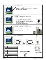
Page 5: ...ion inside a control panel Parts Included SJE Panel Link Premium 100 150 200A Current Transducer Premium version only SJE Panel Link TM ID 640012L SJE Panel Link TM ID 64000P SJE Panel Link Light or 2 SJE Panel Link NEMA 4X Panel For installation outside a control panel or for retrofit applications Includes 10X8X6 NEMA 4X thermoplastic enclosure SJE Panel Link DC Power supply and battery backup Th...

Page 6: ... through the top or side enclosure wall Use with steel stainless steel enclosure or when signal is weak 1m cable with SMA connector Surge Protector Option Mounts on a 1 5 2 0 pole Pole not included Part Assembly part numbers 1038899 ANTENNA ASSEMBLY 40FT PUMP WATCH Assembly Includes 1038516 ANTENNA CELL PENTA BAND OUTDOOR 1038517 BULKHEAD ADAPTOR N FEMALE TO SMA FEMALE 1038518 CABLE ASSY MA MALE T...

Page 7: ...e City of Fargo First Name Example John Last Name Example Doe Email Address Example jdoe cfargo gov Phone Example 123 456 7890 Billing Address Example 1234 Elm St City State Zip Example Fargo MN 58102 Login User Name Example Fargo123 Pump Watch Unit ID Example 68023 FAQ Who should use this form End Users who wish to create an account for monitoring Panel Link units End Users will be responsible fo...

Page 8: ...ON Premium version only SJE Panel Link TM ID 640012L SJE Panel Link TM ID 64000P SJE Panel Link Premium SJE Panel Link Light No analog terminals Two analog inputs Light Unit ID SJE Panel Link TM ID 6400018G SJE Panel Link Gateway Gateway Unit ID Premium Unit ID ...

Page 9: ...SJE 6 SJE Panel Link RTU User Manual POWER 0V GATEWAY 4 3 2 1 12 Battery ON OFF BATT ON OFF SJE PANEL LINK FEATURES ...

Page 10: ...TM MOUNTING THE SJE PANEL LINK RTU 5 5 W x 4 5 H x 3 5 D with antenna at 90 degrees as shown Can be din rail mounted or panel mounted with 4 screws SJE 7 SJE Panel Link RTU User Manual ...

Page 11: ...This battery will enable operation during power loss 24 Vdc and send out alert notifications for power loss and any digital input alerts Note The battery is not able to power the 4 20mA loop sensor Digital inputs only This battery is shipped disconnect and must be turned ON when starting up the device Legacy version external battery New version ...

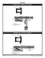
Page 12: ...P 2 RUNNING ALARM 1 ALARM 2 ALARM 3 ALARM 4 COM COM P1 P2 A1 A2 A3 A4 IN2 IN1 NC C NO 0V 24 BACKUP BATTERY CONNECTION SJE PANEL LINK SJE PANEL LINK LIGHT RTU SCHEMATIC 24 VDC Supply Power REMOTE ACTIVATION CONTACTS NON POWERED TORQUE TO 4 4 7 1 IN LBS ATTENTION CONNECT CONTACT CLOSURE INPUTS TO NON POWERED CONTACTS ONLY PUMP 1 RUNNING PUMP 2 RUNNING ALARM 1 ALARM 2 ALARM 3 ALARM 4 COM COM P1 P2 A1...

Page 13: ... ESC PRESS FOR ENTER TM When using the SJE Panel Link Gateway with the TPC X controller the following functions are not available Current monitoring there is no analog input on the conroller for motor Amps Today s Cycle Starts and Runtime The previous 24h total is displayed the controller does not have Real Time Clock ...

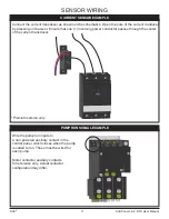
Page 14: ...r Ensure that one 1 incoming power conductor passes through the center of the current transducer PUMP RUN SIGNAL EXAMPLE Wire the pump run inputs to a non powered auxiliary contact in the control panel which closes when the pump is called to run These must be wired for each pump Motor contactor auxiliary contacts for reference only Actual contactor configuration may differ Premium version only ...

Page 15: ...lid base such as treated posts with a treated plywood overlay Mounting on Unistrut or other metal structure is also common Please use the appropriate hardware for securely anchoring the panel to the metal structure TM 8 5 Enclosure Width 11 125 Mounting Screws 10 5 Enclosure Height 5 625 Mounting Screws 6 3 Depth ...

Page 16: ...se liquid tight conduit or strain relief fittings Liquid tight conduit fittings Liquid tight conduit OR CONDUIT OPTIONS Use liquid tight fittings and conduit to run cables between the SJE Panel Link and the Lift Station control panel Do not run conduit from the SJE Panel Link to the wet well Conduit TM ...

Page 17: ...SJE 14 SJE Panel Link RTU User Manual SYSTEM VIEW SJE PANEL LINK INSTALLATION EXAMPLE 6 7 F T TM TM 6 7 F T ...

Page 18: ...SJE 15 SJE Panel Link RTU User Manual WIRING SCHEMATIC SJE PANEL LINK SJE Panel Link SJE Panel Link Premium is shown above See pages 8 and 9 for additional versions ...

Page 19: ...ve the input terminal The relay output also has an LED indication See page 12 for details RTU COMMUNICATION The user can check the RTU signal strength RSSI on the web portal Hover your cursor over the signal strength icon on the top of the main screen RSSI THRESHOLDS RSSI is a measurement of the power present in a received radio signal Received Signal Strength Indicator The larger the number the b...

Page 20: ...o verify and activate your account After logging in again you will need to agree to the Terms of Use These steps only need to be completed during the initial setup and activation of your account Notes The end User should activate this product When the initial 1 year of cellular service comes to an end AMI will contact you directly and review renewal options The primary User Account Admin will be a...

Page 21: ...User can only be assigned to one Account Create Accounts Create Account Admins Create Users Assign Gateways to Accounts Place Gateways on Map 1 Configure Gateways 2 Name Gateways Search Gateways View Gateway Data Run Reports Dealer X X X X X X X X X X Account Admin3 X X X X X X User X X X 1 With privileges assigned 2 With privileges assigned 3 Account Admin and User can work within assigned accoun...

Page 22: ...oller From Map Satellite or road view available From List From Tree View Search by RTU Name or ID Sort by RTU Name or ID FROM MAP When you log in the interactive map appears on the main screen If your RTU s have already been located on the map it will appear here the next section explains how to place the RTU on the map Click on a controller to see the device ID and other pertinent information To ...

Page 23: ...tly displayed and can be clicked at any time to move from one RTU to another To select an RTU from the Tree View click on the RTU icon SEARCHING AND SORTING BY RTU ID OR NAME Select the List view from the Dashboard to search devices based on any of the top row items Device ID Device Name Account Name etc Panel Link Icons ...

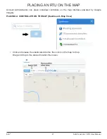
Page 24: ...ount Adminstrators can place individual controllers on the map interface powered by Google Imagery PLACING A CONTROLLER ON THE MAP Dashboard Map View Click and release the unallocated device then click on the map to drop Drag and drop to the desired location then save ...

Page 25: ...P Click at the top right of the page and select Users Once a new user account is created an email will be sent to the new user s email address The user will have 48h to use the link on the email to verify the information listed above This verification process is in place to ensure that new users are aware and willing to receive future alarm notifications If the user account is not verified the not...

Page 26: ...perly configured The functionality of this system is dependent on the setup of the RTU SJE 23 SJE Panel Link RTU User Manual The data on the screen may not display the latest RTU values Use the Get Status button to read the most current values ...

Page 27: ...SJE Panel Link RTU User Manual Click to store changes It will take a few seconds to take effect RTU SETUP Click on the Setup button on the top row of the Main Screen to enter the RTU edit screen General Setup ...

Page 28: ...ert the selected user if the RTU is no longer On line not connected to the server This can be as a result of power loss for a prolonged time or a drop in cellular service It can take the server up to 20 minutes to detect this condition ONLINE OFFLINE TRIGGER ALERT SETUP The SJE Panel Link has the ability to alert the user when the RTU transitions from online to offline and offline to online Click ...

Page 29: ... set time see Configuration screen The 3 7 Vdc battery must be connected P1 2 Runtime Alarm The pump ran continuously for longer than the set time see Configuration screen This condition may indicate a pump clog a high in flow event or sensor fault Premium Version Additional Alarms Xdcr High Level transducer High Level alarm This alarm set point and timer value is set in the configuration screen T...

Page 30: ...t wish to use this function STATION DATA trending available see Report Trending section Wet Well Level Level of the wet well as measured by the transducer P1 2 Amps Pump Current snapshot captured 30 secs after motor start by the current transducer Not available when using the TPC X controller P1 2 Cycles The number of start cycles occurred since midnight Note When using the SJE Panel Link Gateway ...

Page 31: ... This function enables you to change the text on the screen to match the function of the alarm assigned in the field Example SJE 28 SJE Panel Link RTU User Manual You can now edit the text labels with the red boxes To save changes press to cancel edits press ...

Page 32: ...he presence of a high level measurement from the transducer This alarm is triggered by the High Tank Level value 5 Sec Low Tank Level Alarm delay Delay timer used to confirm the presence of a low level measurement from the transducer This alarm is triggered by the Low Tank Level value 5 Sec Acknowledge Alarm delay If an alarm becomes active the timer starts and the operator must click the button o...

Page 33: ...er pump cycle has been exceeded This alarm requires the user to click on the to clear 30 min P1 P2 High Amp Max timer value for pump runtime during a single cycle The RTU is equipped with a maximum run time indicator The unit can be configured to activate a message if a pre determined maximum run time per pump cycle has been exceeded This alarm requires the user to click on the to clear 80A P1 P2 ...

Page 34: ...ycle Tank Diameter Enter the tank diameter in Ft Flow Calc Start Level See below in Ft Flow Calc Stop Level See below in Ft Important notes on flow setup Set Flow Calc Start Level at least 4 below the pump start level Set Flow Calc Stop Level at least 4 above the pump stop level The flow accuracy is better with longer cycle times 2 minutes or more SJE 31 SJE Panel Link RTU User Manual When using a...

Page 35: ...er In addition to the original SMS message you can assigned escalated users The escalation can happen 2 ways forced or timed The forced will be initiated by the users who receive the initial SMS by texting a code that will escalate to the assigned user ALARM NOTIFICATION SETUP You have three options to receive alerts Email 1 Email 2 and SMS The user phone number needs to be setup on the users tab ...

Page 36: ...ed when the alarm goes ON condition set Alert and when the alarm goes OFF condition reset alert Multiple Users may be selected for notification To create additional Users see NEW USER SETUP on page 19 Type in the Alert text message that will be delivered You do not need to include the name of the station in the text as it is always sent as part of the notification CONNECTING ALERTS TO USER ...

Page 37: ...en when the initial user does not acknowledge the message The escalation time is fixed at 30 minutes EMAIL NOTIFICATION EXAMPLE EMAIL TO TEXT It is possible to convert an email into a SMS Text This function is made available by some cellular carriers Please check with your carrier for more information Below are some examples AT T cellnumber txt att net Verizon cellnumber vtext com T Mobile cellnum...

Page 38: ...1 10 2014 8 57 youremail server com Alert Controller 7160 LS 10 St Pete Beach 8 High Level Float Reset 1 10 2014 8 52 1 10 2014 8 50 youremail server com Alert Controller 7160 LS 10 St Pete Beach 4 Power Fail Rest 1 10 2014 8 50 1 10 2014 8 50 youremail server com Alert Controller 7160 LS 10 St Pete Beach 8 High Level Float 1 10 2014 8 36 1 10 2014 8 26 youremail server com Alert Controller 7160 L...

Page 39: ...s SMS lists all notifications sent via SMS to a smart device Reports are very useful for evaluating the health of the pumping station and for detecting abnormal operation Example High inflow from water infiltration from a storm or other event This data can be downloaded in various format and shared Click on the Report icon on top of the screen and select the type of report to view Example Click on...

Page 40: ...he graph Click on Reset zoom to go back to the previous view Click on to create the graph SJE 37 SJE Panel Link RTU User Manual You can view all graphs at the same time Click on the data labels below the graph to turn OFF the pens you do not wish to display This enables you to compare data Example P1 and P2 Amps Click on to view export options Click on label to turn OFF pen ...

Page 41: ...accumulation data select Accumulation This function is used to view Run times Cycles on select versions When you are finished with your session please logout of the system SJE 38 SJE Panel Link RTU User Manual ...

Page 42: ...eby agree as follows 1 Customer agrees to pay AMI for hardware and monthly monitoring fees as defined in AMI invoices and AMI agrees to provide Customer with monitoring and notification services by utilizing automated texting e mailing and or TCP IP transfer of data to Customer s designated destinations as set forth in the AMI web site database on a best efforts basis For additional operational an...

Page 43: ...ces and that customer should make provisions for alternate means of remotely or locally operating said controls AMI strongly recommends that Customer make electrical or mechanical provisions at the remotely controlled site equipment that will alleviate or reduce the risks associated with the failure by AMI to properly control said remote relay control functions Customer understands and acknowledge...

Page 44: ... Reserved PN 1052700B 04 19 Manufactured by SJE Inc Technical support 1 800 746 6287 techsupport sjeinc com 22650 County Highway 6 Detroit Lakes Minnesota 56501 USA www csicontrols com www primexcontrols com www sjerhombus com ...

Reviews: