1
2
3
213--- 47
Fuel System
13---26
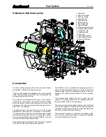
F. Adjusting low idling speed
1. Low idling speed
2. Revolution lever
3. Max. revs
The low idling speed can be adjusted with a limiting screw
in front of the revolution lever. The adjusting screw for max.
revs has been sealed. This adjustment has been done in
the factory, and adjustment of max. revs afterwards is pro-
hibited.
Note!
The throttle cable is attached to the revolution lever
lower hole. To the upper hole is fastened a return spring.
Other information
The injection pump housing upper cover has been sealed
to prevent adjustment of engine output afterwards. Also the
stop solenoid is fitted under this cover. It is recommended,
that all pump repairs are made by an authorised Stanadyne
workshop.
G. Bleeding Thermostart system
Always remove air from the glow plug fuel pipe when the
pipe or reservoir has been emptied during repair work etc.
This prevents damages to the glow plug caused by lack of
fuel during starting.
1. If the reservoir is empty, fill it e.g. with a drip pot through
the breather hole on the reservoir.
2. Open the glow plug pipe connector and drain fuel from
the pipe. Connect the pipe.
H. Wiring diagram of electrical ad-
vance (CCA)
+
W
OUT
---
+
Ignition switch
W
(R)
Green 1,5 mm
Control unit
Injection pump
Alternator
Blue 1,5 mm
Red 1,5 mm
Brown 1,5 mm
2
2
2
2
Stop solenoid
213--- 48
The control unit of the electrical advance depends on gear
ratio of the alternator.
SPARE PART
NO
GEAR
RATIO
ALTERNA-
TOR
8368 54777
2.32
12 V MM
8368 54778
2.90
12 V Delco
8368 54817
3.97
12 V Valeo

