


20--- 13
20--- 13/1
Construction
0---19
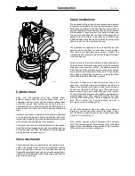
Inlet and exhaust system
The filter system for the engine inlet air comprises a cyclone
type precleaner, and a paper filter which acts as the main filter.
The incoming air is made to rotate in the cyclone precleaner.
This causes most of the impurities to settle out and collect in
the cyclone precleaner dust collector. The paper filter com-
prises one or two replaceable filter elements. The paper is
corrugated and surrounded by a metal support.
The impurities in the air collect at the larger filter element
which can be cleaned when necessary. The inner safety filter
prevents impurities form entering the engine should the main
filter element break, or be fitted incorrectly.
A mechanical or electrical service indicator can be mounted
on the filter housing or on the inlet pipe to show when the filter
cartridge is clogged. The inlet system also includes the hoses
between the air cleaner and the turbocharger and the turbo-
charger and the intake manifold.
The exhaust manifold is attached to the cylinder head with
high tensile bolts without a separate gasket. Retightening of
the manifold bolts is unnecessary.
In the marine--- and generator engines a liquid cooled exhaust
manifold is used, that is connected to the engines cooling
liquid circulation (so---called freshwater circulation). These
exhaust manifolds are sealed from the liquid circulation part
with o---rings in 420---engines and with level seals in
320/620/634---engines.
The turbocharger is turbo---compressor driven by exhaust
gas. The compact design of the turbocharger is sensitive to
react even during low revolutions. The turbocharger is lubri-
cated and cooled by the lubrication system of the engine.
DW/DWI engine is equipped with a by---pass turbocharger
where the highest air pressure is adjusted by so---called by---
pass channel.
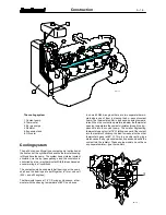
The compressed air is cooled by the air to water basis. The air
coming from the turbocharger has a temperature about
150
˚
C which is cooled by the cooling water of the engine
down to about 95
˚
C.
The cooling cell is installed on the intake manifold and con-
nected to the engine cooling system. The cooling of the com-
pressed air stabilised the combustion, irrespective of the tem-
perature, and minimises the thermal and mechanical load of
the engine thus lowering nitric oxides (NO
x
).


