


213--- 41
Fuel System
13---22
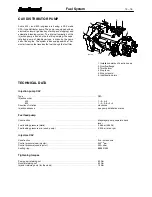
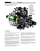
Stanadyne distributor pump
1. Drive shaft
2. Governor weights
3. Governor spring
4. Stop solenoid
5. Overflow valve
6. Metering valve
7. Cam ring rollers
8. Hydraulic head
9. Pressure regulator valve
10. Transfer pump blades
11. Distributor rotor
12. Pressure valve
13. Cam ring
14. Automatic advance
15. Centrifugal governor
16. Pumping plungers
Construction
The main rotating components are the drive shaft, transfer
pump blades, distributor rotor and governor.
The drive shaft engages the distributor rotor in the hydraulic
head. The drive end of the DB2 rotor incorporates two
pumping plungers and DB4 four.
The plungers are actuated toward each other simulta-
neously by an internal cam ring through rollers and shoes
which are carried in slots at the drive end of the rotor. The
numbers of cam lobes normally equals the number of cylin-
ders (not 3---cyl. engines).
The transfer pump at the rear of the rotor is of the positive
displacement vane type and is enclosed in the end cap.
The end cap also houses the fuel inlet strainer and transfer
pump pressure regulator. The face of the regulator assem-
bly is compressed against the liner and distributor rotor and
forms an end seal for the transfer pump.
The injection pump is designed so that end thrust is against
the face of the transfer pump pressure regulator.
The distributor rotor incorporates two charging ports and a
single axial port (pressure chamber), in which is placed the
pressure valve. After the delivery valve, there is one dis-
charge port to serve all head outlets to the fuel injection
pipes.
The hydraulic head contains the bore in which the rotor
revolves, the metering valve bore, the charging ports and
the connections to the fuel injection pipes.
The pump contains a mechanical governor. The centrifugal
force of the weights is transferred to the metering valve via
a linkage. The metering valve can be closed electrically with
aid of the solenoid in the pump housing.
The automatic advance is a hydraulic mechanism which
turns the cam ring and advances or retards the beginning
of the fuel delivery from the pump.


