SIP HG3000S SWF Assembly Instructions Manual Download Page 18

18 

  ASSEMBLY INSTRUCTIONS….cont 

Danger: 

Ensure that the gas pipe is secure and leak free before operation. 

Connect both parts at the opposite end of the interconnecting cable to the 

front of the welder (see below).  

Align the 2 torch pins on the welding torch with the 2 connector holes on the euro 

adaptor. 
Push the welding torch in to the euro adaptor. 
Screw the torch locking ring on to the euro adaptor and tighten to secure. 

Locking ring 

Euro adaptor 

Torch pins 

Holes 

   CONNECTING THE TORCH 

Note: 

Connect  the  lead  to  the  positive  (+)  terminal  for  standard  welding 

and negative (-) for flux cored welding. 

19 

  ASSEMBLY INSTRUCTIONS….cont


Lift up the wire spool cover. 
Turn the wire retaining nut clockwise to loosen and remove it. 


Retaining Nut 

Fit  the  welding  wire  over  the  spool  holder  so  that  the  wire  will  feed  from  the    

bottom of the roll.  
Refit the retaining nut, and secure in place by tightening it. 
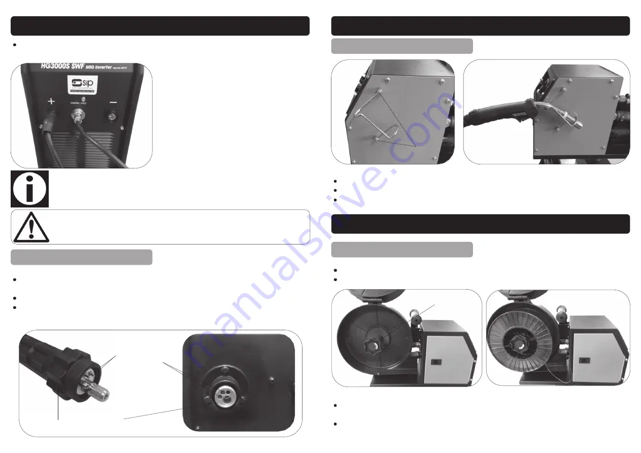
Retaining Screws 

Loosen the torch holder retaining screws.  
Fit the torch holder.  
Retighten the retaining screws. 

   FITTING THE TORCH HOLDER 

   LOADING THE WIRE 

  OPERATING INSTRUCTIONS


Summary of Contents for HG3000S SWF

Page 1: ...supplier offers a disposal facility please use it or alternatively use a recognised re cycling agent This will allow the recycling of raw materials and help protect the environ ment FOR HELP OR ADVICE...

Page 2: ...t the Product Enquiry HG3000S SWF Mig Inverter Welder SIP Part No 05777 Conforms to the requirements of the following directive s as indicated 2006 95 EC Low Voltage Directive 2004 108 EC EMC Directiv...

Page 3: ...Contents and Accessories 15 Getting to Know Your Welder 17 Assembly Instructions 19 Operating Instructions 25 Maintenance 26 Troubleshooting 27 Wiring Diagram 28 Exploded Drawing Main Unit 29 Parts L...

Page 4: ...applications and limitations as well as the potential hazards spe cific to it KEEP WORK AREA CLEAN AND WELL LIT Cluttered work benches and dark areas invite accidents Floors must not be slippery due...

Page 5: ...harp edges If the mains lead is damaged it must be replaced by the manufacturer or its service agent or a similarly qualified person in order to avoid un wanted hazards All extension cables must be ch...

Page 6: ...a competent electrician or engineer Ensure that the machine is connected to the correct supply voltage and protected by a fuse or circuit breaker of the recommend rating Never allow the earth clamp a...

Page 7: ...electric shock hazard Avoid the possibility of the welding current passing through lifting chains crane cables or other elec tric paths Frequently inspect leads for wear splits cracks and any other d...

Page 8: ...lding gauntlet gloves should be worn to protect the hands from burns non synthetic overalls with buttons at the neck and wrist or similar clothing should be worn Greasy overalls should not be worn Wea...

Page 9: ...r for beryllium both must be used Metals coated with or containing materials that emit toxic fumes should not be heated unless coating is removed from the work surface The area should be well ventilat...

Page 10: ...r that common sense and caution are factors which can not be built into this product but must be applied Vapours from chlorinated solvents can be decomposed by the heat of the arc or flame to form pho...

Page 11: ...cian Connecting to the power supply The HG3000S welder is supplied without a plug fitted it must not be connected to a standard 13A supply Consult the technical specification table page 13 for the re...

Page 12: ...to the input current required to run the inverter welder it is advisa ble not to use an extension lead Note Always make sure the mains supply is of the correct voltage and the correct fuse type and ra...

Page 13: ...C Caution Ensure all protective equipment is worn and bystanders are not in the vicinity Note In order to arc MMA weld with the welder you will need to purchase an electrode holder and lead SIP part n...

Page 14: ...and values given are an indication only These welding current values are for the E6013 electrodes for other types of electrode consult their data sheet Electrode Size mm Material Thickness mm Welding...

Page 15: ...be increased If the welder has an erratic sound and the torch feels that the wire is hitting against the work then you have the wire feed speed to high and it should be reduced when the wire feed spee...

Page 16: ...pressure adjustment knob back over the tension arms Screw the pressure adjustment knob down but not too tight as it will crush the wire Plug the welder in to the mains supply and turn it on Lay the m...

Page 17: ...free end of the Mig wire from the side of the wire spool trim off the distorted end of the wire with a pair of wire cutters Hold the wire carefully as it will try to unwind from the spool Pressure adj...

Page 18: ...ing Euro adaptor Torch pins Holes CONNECTING THE TORCH Note Connect the lead to the positive terminal for standard welding and negative for flux cored welding 19 ASSEMBLY INSTRUCTIONS cont Lift up the...

Reviews: