background image


25


4.2.3 Battery mode 

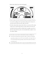
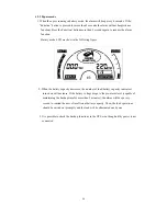
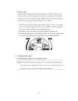
When operating in bypass mode set up through WinPower software, the display on the 

front panel is show in the following diagram. The utility power indicator and the bypass 

indicator are turn on. The load/battery capacity indicator will be turned on in accordance 

with the load capacity connected. The UPS beeps every 2 seconds. 


1. If the utility power indicator blinks, it shows that the voltage or frequency of the utility 

power is out of the input range of the UPS or there are problems with reversed polarity 

(L/N) of site wiring or disconnect to the ground for protection. 

2. Other display on the front panel is same as those mentioned in normal mode. 

3. When operating in bypass mode, the backup function of the UPS is not available and the 

power used by the load is directly from the utility power via internal EMI filter. 


4.3  Operating Instructions 

4.3.1 Turning On and Completely Powering Down the UPS 

Note

: 

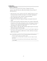
The battery is fully charged before delivery. However, storage and transportation will 

inevitably cause some charge loss. Therefore, it is advisable to charge the battery for 10 

hours before using it, so as to ensure adequate battery autonomy. 


Summary of Contents for PANTHER 10KR

Page 1: ...1kVA 10kVA 1 Phase In 1 Phase Out Sinercom srl Headquarter Via G Cappalonga 9 A 00043 Ciampino Rm Italy tel 39 06 79800323 fax 39 06 79814644 Factory Via Cascina Secchi 247 4b 24040 Isso BG tel 39 03...

Page 2: ...2 Thank you for purchasing product Observe the warnings on the machine and manual strictly and properly keep the manual Do not operate the UPS before read safety notes and operation instructions...

Page 3: ...Battery for Long Backup Time UPS 14 3 3 3 Connecting Communication Cable 15 4 Operation 20 4 1 Introduction of Display Panel 20 4 2 Operation Mode 22 4 2 1 Normal mode 22 4 2 2 Bypass mode 24 4 2 3 Ba...

Page 4: ...ispose with ordinary trash 1 2 Safety Instructions 1 Read this manual carefully and thoroughly before operation the UPS and save this manual properly for future reference 2 Do not tear up or shatter t...

Page 5: ...nd other inlets 9 Do not store or use the device in the following environment Where there is inflammable gas corrosive agents or heavy dust Where the temperature is very high or low above 4 0 or below...

Page 6: ...anufacture education and so on 2 1 System Type and Configuration There are two types of UPS according to the battery configuration standard type and long backup time type each available in the followi...

Page 7: ...5 2 2The Appearance of the UPS 1 Front view Figure 2 1 PANTHER 2U Figure 2 2 PANTHER 3U 2 Rear view Figure 2 3 The rear panel of PANTHER 1KR XL...

Page 8: ...6 Figure 2 4 The rear panel of PANTHER 2KR Figure 2 4 The rear panel of PANTHER 2KR XL Figure 2 6 The rear panel of PANTHER 3KR Figure 2 5 The rear panel of PANTHER 3KR XL...

Page 9: ...7 Figure 2 7 The rear panel of PANTHER 6KR Figure 2 8 The rear panel of HP9115CRT 10K...

Page 10: ...8 Figure 2 9 The front external view 2 3 Operating Principle 1 3kVA Figure 2 10 The UPS operating principle...

Page 11: ...rough the DC DC converter 5 Bypass It is very important in the UPS system In the event of an UPS fault that will not lead to UPS shutdown the load will be automatically transferred to the bypass Meanw...

Page 12: ...l 1 Pcs A Winpower software CD 1 Pcs standard long backup Model 6KR XL 10KR XL External Battery Cable 1 Pcs 3 2 Installation Notes 1 When locating the UPS make sure there is no hazardous objects aroun...

Page 13: ...ins input Figure 3 1 Connection Method of Input for PANTHER 1KR XL 3KR XL 2 Output cable connection Table 3 2 Output way of UPS Rating Model Quantity of output socket Output Terminal Block 1kVA PANTHE...

Page 14: ...rrent over 10A recommended The wring configuration is shown in the following diagram 1 Remove the cover of the terminal block 2 Use AWG14 2 1mm wires for wiring configuration 3 Upon completion of the...

Page 15: ...6KR XL use AWG10 5 3mm wires for wiring configuration PANTHER 10KR XL use AWG10 8 4mm 3 Upon completion of the wiring configuration please check whether the wires are securely affixed 4 Put back the t...

Page 16: ...or connecting the battery pack 6 10kVA Refer to Figure3 4 3 Connect the external battery cable to the battery terminal DO NOT connect the battery socket of the UPS first Otherwise it may cause electri...

Page 17: ...ication Intelligent Slot It is designed for installing the AS400 card SNMP card and CMC card You can choose for one of them to installed a AS400 You can utilize AS400 s monitor function to manage the...

Page 18: ...ost reliable power supply structure N represents the minimum UPS number that the total load needs X represents the redundant UPS number i e the fault UPS number that the system can handle simultaneous...

Page 19: ...nt battery pack 5 Please refer to the wiring diagram in the next page and opt suitable breaker The requirement of the output wiring is as follows When the distance between the UPSs in parallel and the...

Page 20: ...18...

Page 21: ...tially in Line mode 3 Shutdown the units shut down sequentially in INV mode When the last one completes the shutdown action e ach unit will shut down the inverter simultaneously an d transfer to Bypas...

Page 22: ...Enter button only for 6 10kVA verify the selection 3 Select button Select button main function is 1 If UPS in bypass mode or no output model the button can be used to enter setup mode to choose UPS ou...

Page 23: ...us this light bright Trouble light When the fault occurs this light bright Input information Display input voltage Display voltage range 0 999 VAC Display input voltage Display voltage range 0 00 99 9...

Page 24: ...VAC 220VAC 230VAC under No output mode or bypass mode Choose UPS output frequency choose anyone frequency 50Hz or 60Hz under No output mode or bypass mode Choose buzzer switch choose buzzer opening an...

Page 25: ...If the connection between battery and UPS is confirmed without any problem it may be due to the defect or aging of the battery please refer to the troubleshooting in chapter 6 to solve the problem acc...

Page 26: ...ng figure 2 When the battery capacity decreases the number of load battery capacity indicators turned on will decrease If the battery voltage drops to the pre alarm level capable of maintaining the ba...

Page 27: ...S or there are problems with reversed polarity L N of site wiring or disconnect to the ground for protection 2 Other display on the front panel is same as those mentioned in normal mode 3 When operati...

Page 28: ...r With no mains input feed to the UPS hold and press the ON OFF button for 1 second until the buzzer beeps In the power on process the UPS has the same operation as if it is connected to utility power...

Page 29: ...ery self diagnosis to check the battery conditions There are two methods to initiate the battery self diagnosis 1 Through the function button In normal mode press and hold the function for more than 2...

Page 30: ...ng error 5 UPS voltage 15 Overload 6 Inverter fault 7 NTC open 8 Other fault Error code and warming code for PANTHER 6KR XL 10KR XL Error code Description Warming code Description 1 Communication erro...

Page 31: ...own automatically in the course of discharging In the regions of hot climates the battery should be charged and discharged every 2 months Moreover the standard charging time should be not less than 10...

Page 32: ...S should operate in battery mode In both cases there should be no fault indication 2 Check the transfer between the UPS operation modes Disconnect the main input to simulate a mains failure the UPS sh...

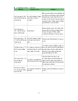
Page 33: ...The charger of the UPS is defective Please contact the distributor or Service center Display fault 8 buzzer long Internal fault Please contact the distributor or Service center Display fault 13 buzzer...

Page 34: ...06 the UPS beeps continuously The UPS transfers to fault mode due to its internal fault Please contact the distributor or service center The Mode code is 03 UPS turn into Battery mode The voltage or...

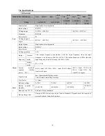
Page 35: ...he input frequency when the input frequency is in the range of 46 Hz 54 Hz 2 The output frequency is 50Hz when the input frequency is not in the range of 46 Hz 54 Hz Battery mode 50 0 2 Hz Inverter ov...

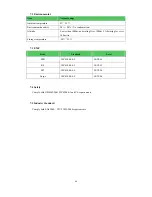
Page 36: ...ating Over 1000m 1 derating for every 100m rise Storage temperature 15 45 7 3 EMC Item Standard Level ESD I EC61000 4 2 LEVEL4 RS I EC61000 4 3 LEVEL3 EFT I EC61000 4 4 LEVEL4 Surge I EC61000 4 5 LEVE...

Page 37: ...3 years This limited warranty does not apply to conditions as follows Man made fault Out of warranty The finished product of which the serial number is changed or lost Damage or loss resulted from fo...

Reviews: