Sinclair ASH-09AIM PT Service Manual Download Page 38

33

Installation and Maintenance

Service Manual

NO.

Malfunction

Name

Display Method of Indoor Unit

Display Method of Outdoor 

Unit

A/C status

Possible Causes 

Dual-8

Code

Display

Indicator Display (during 

blinking, ON 0.5s and OFF 

0.5s)

Indicator has 3 kinds of 

display status and during 

blinking, ON 0.5s and OFF 

0.5s

Operation

Indicator

Cool

Indicator

Heating

Indicator

Yellow

Indicator

Red

Indicator

Green

Indicator

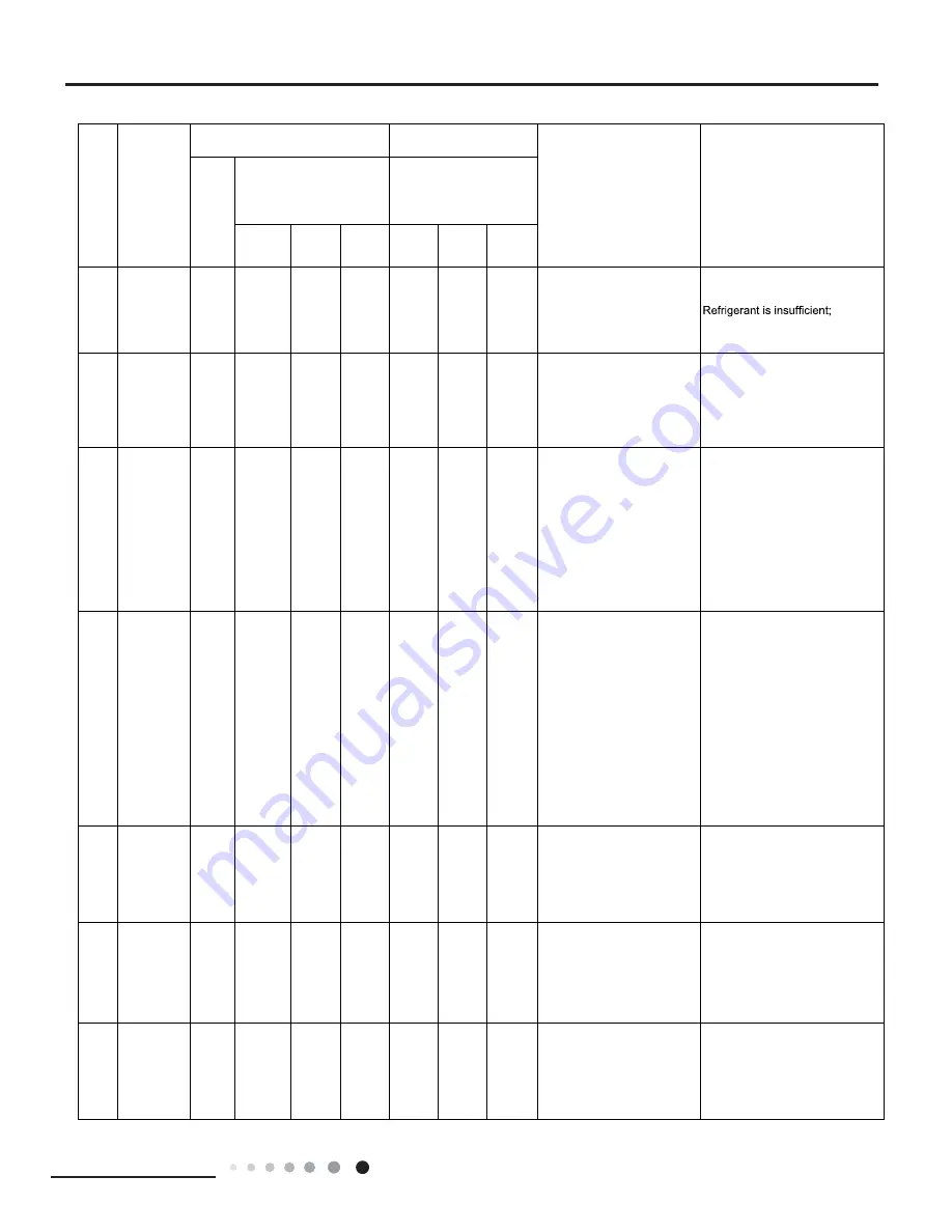
19

Decrease

frequency 

due to

high air

discharge

F9

OFF 3S

and blink

9 times

OFF 1S

and 

blink

twice

All loads operate normally, 

while

operation frequency for

compressor is decreased

Overload or temperature is too 

high; 

Malfunction of electric expansion 

valve (EKV)

20

Limit/

decrease

frequency 

due to

antifreezing

FH

OFF 3S

and blink

2 times

OFF 3S

and blink

2 times

OFF 1S

and 

blink

4 times

All loads operate normally, 

while operation frequency for 

compressor is decreased

Poor air-return in indoor unit or fan 

speed is too low

21

Voltage for 

DC bus-bar 

is too high

PH

OFF 3S

and blink

11 times

OFF 1S

and 

blink

13 times

During cooling and drying

operation, compressor will stop

while indoor fan will operate;

During heating operation, the

complete unit will stop 

operation.

1. Measure the voltage of position 
L and N on wiring board (XT), if the 
voltage is higher than 265VAC, turn 
on the unit after the supply voltage 
is increased to the normal range.
2.If the AC input is normal, 
measure the voltage of electrolytic 
capacitor C on control panel (AP1), 
if its normal, theres malfunction 
for the circuit, please replace the 
control panel (AP1)

22

Voltage of 
DC bus-bar 
is too low 

PL

OFF 3S

and blink

21 times

OFF 1S

and 

blink

12 times

During cooling and drying
operation, compressor will stop
while indoor fan will operate;
During heating operation, the
complete unit will stop

1. Measure the voltage of position 

L and N on wiring board (XT), if the 

voltage is higher than 150VAC,

turn on the unit after the supply 

voltage is increased to the normal 

range.

2.If the AC input is normal, 

measure the voltage of electrolytic 

capacitor C on control panel (AP1), 

if its normal, theres malfunction 

for the circuit, please replace the 

control panel (AP1)

23

Compressor 
Min 
frequence in 
test state

P0

(during 

blinking, 

ON 

0.25s 

and OFF 

0.25s)

(during 

blinking, 

ON 

0.25s 

and OFF 

0.25s)

Showing during min. cooling or 

min. heating test

24

Compresso r 
rated 
frequenc e in 
test state

P1

(during 

blinking, 

ON 

0.25s 

and OFF 

0.25s)

(during 

blinking, 

ON 

0.25s 

and OFF 

0.25s)

Showing during nominal cooling or 
nominal heating test

25

Compressor 
maximum 
frequence in 
test state

P2

(during 

blinking, 

ON 

0.25s 

and OFF 

0.25s)

(during 

blinking, 

ON 

0.25s 

and OFF 

0.25s)

Showing during max. cooling or 

max. heating test

Summary of Contents for ASH-09AIM PT

Page 1: ...SERVICE MANUAL ASH 09AIM PT ASH 13AIM PT MATRIX SERIE ...

Page 2: ......

Page 3: ...emperature Tj EN 14825 2012 MATRIX SERIE 35 2 6 4 0 7 8 2 4 2 8 30 2 0 5 8 2 1 1 5 4 2 25 1 2 8 5 7 6 1 0 4 5 20 1 1 9 3 12 11 1 1 5 8 35 3 5 3 7 7 8 3 0 2 7 30 2 6 5 8 2 1 1 9 4 2 25 1 7 8 5 7 6 1 2 4 8 20 1 1 9 0 12 11 1 0 5 5 27 19 20 27 19 20 ASH 09AIM PT ASH 13AIM PT 35 5 3 3 0 7 8 4 7 2 6 30 3 9 4 2 2 1 2 9 3 8 25 2 5 5 8 7 6 1 9 4 8 20 1 1 8 4 12 11 0 8 5 5 35 6 2 3 2 7 8 5 2 2 3 30 4 4 4 8...

Page 4: ...Unit 6 3 2 Outdoor Unit 6 4 Refrigerant System Diagram 8 5 Electrical Part 9 5 1 Wiring Diagram 9 5 2 PCB Printed Diagram 11 6 Function and Control 13 6 1 Remote Controller Introduction 13 6 2 Brief Description of Modes and Functions 17 Part Ċ Installation and Maintenance 22 7 Notes for Installation and Maintenance 22 8 Installation 24 8 1 Installation Dimension Diagram 24 8 2 Installation Parts c...

Page 5: ...9 3 Troubleshooting for Normal Malfunction 51 Exploded View and Parts List 53 Indoor Unit 53 Outdoor Unit 55 10 Removal Procedure 59 10 1 Removal Procedure of Indoor Unit 59 10 2 Removal Procedure of Outdoor Unit 64 Appendix 69 Appendix 1 Reference Sheet of Celsius and Fahrenheit 69 Appendix 2 Con guration of Connection Pipe 69 Appendix 3 Pipe Expanding Method 70 Appendix 4 List of Resistance for ...

Page 6: ...1 Technical Information Service Manual 1 Summary Indoor Unit Outdoor Unit ASH 09AIM PT ASH 13AIM PT ASH 09AIM PT ASH 13AIM PT Remote Controller YAA1FB Part ĉ Technical Information ...

Page 7: ...ication Area m2 12 18 16 24 Fan Type Cross ow Cross ow Diameter Length DXL mm ĭ92X645 ĭ92X645 Fan Motor Cooling Speed SH H M L SL r min 1260 1050 900 690 1290 1070 900 690 Fan Motor Heating Speed SH H M L SL r min 1320 1200 1000 910 1280 1050 980 920 Output of Fan Motor W 20 20 Fan Motor RLA A 0 10 0 10 Fan Motor Capacitor ȝF 1 0 1 0 Input of Heater W Evaporator Form Aluminum Fin copper Tube Alumi...

Page 8: ...Motor Speed rpm 900 850 Output of Fan Motor W 30 30 Outdoor Fan Motor RLA A 0 13 0 23 Unit Fan Motor Capacitor ȝF Air Flow Volume of Outdoor Unit m3 h 1800 2000 Fan Type Axial ow Axial ow Fan Diameter mm ĭ400 ĭ445 Defrosting Method Automatic Defrosting Automatic Defrosting Climate Type T1 T1 Isolation I I Moisture Protection IP24 IP24 Permissible Excessive Operating Pressure MPa 4 3 4 3 for the Di...

Page 9: ...0 100 120 Condition Indoor DB 20 Indoor air flow Turbo Pipe length 5m Voltage 230V Compressor Speed rps Cooling Heating Current A Current A 50 60 70 80 90 100 110 32 33 34 35 36 37 38 39 40 41 42 43 44 45 46 Capacity ratio Condition Indoor DB27 WB19 Indoor air flow Turbo Pipe length 5m Outdoor temp C 0 20 40 60 80 100 120 Capacity ratio Outdoor temp C g n i t a e H g n i l o o C ASH 09AIM PT ASH 1...

Page 10: ...door and outdoor unit Inlet and outlet pipe temperature of heat exchanger Fan speed of indoor unit Fan speed of outdoor unit Compressor revolution Hz Indoor Outdoor P MPa T1 C T2 C 20 7 6 09AIM PT 13AIM PT 2 5 3 0 in 50 80 out 37 43 in 1 3 out 2 5 Turbo Super High 60 80 Instruction T1 Inlet and outlet pipe temperature of evaporator T2 Inlet and outlet pipe temperature of condenser P Pressure at th...

Page 11: ...6 Technical Information Service Manual 3 Outline Dimension Diagram 3 1 Indoor Unit 3 2 Outdoor Unit 69 124 55 55 845 130 542 173 189 275 848 763 540 257 0 4 5 320 6 8 2 ASH 09AIM PT Unit mm ...

Page 12: ...7 Technical Information Service Manual 596 354 838 899 303 378 550 Unit mm ASH 13AIM PT ...

Page 13: ...ng Model Connection pipe speci cation Liquid 1 4 6mm Gas 3 8 9 52mm Indoor unit Outdoor unit COOLING HEATING Accumlator 4 Way valve Discharge Suction Heat exchanger evaporator Heat exchanger condenser Valve Valve Liquid pipe side Gas pipe side Strainer Strainer Electron expansion valve ...

Page 14: ...w Green BK Black VT Violet OG Orange Note Jumper cap is used to determine fan speed and the swing angle of horizontal lover for this model L OUT L1 L1 0 0 RT1 RT2 M JUMP CAP TEM SENSOR ROOM TUBE TEM SENSOR FAN MOTOR SWING MOTOR U D AP2 SWING UD K4 TUBE ROOM AC L PG PGF DISP 1 DISP 2 CN2 CN1 AP1 DISPLAY GENERATOR COOLPLASMA M PE XT1 W1BU W3BN N 1 OUTDOOR UNIT 2 3 COM OUT W4YEGN N W2BK BU YEGN BN L ...

Page 15: ...ENSOR OUTROOM EXHAUST TEM SENSOR TEM SENSOR TUBE L1 L1 L2 L2 L2 W13WH HPP COMP V COMP W COMP M HP EH1 EH2 COMP FAN I N D O O R U N I T CN2 LX 2 W12 W11 LX 1 L WH OG SAT OVC COMP U V W L3 L3 P 4YV XT2 RT3 0 0 RT2 0 RT1 2 3 N 1 OFAN1 E R E C S PE COMP U AP1 W1BN W4BK W2BU W3YEGN W10RD W8YEGN BN BK BU YEGN W5BU W6YE W7RD N1 AC L1 4V AC L2 N2 N3 COMU W9BU EKV CN1 PE PE PE RD RD HEATER COMP HEAT N1 CHA...

Page 16: ...l wire 5 Port of indoor fan 6 Solid state relay 7 Jumper Cap 8 Auto button 9 Feedback of indoor fan 10 Port of motor for vertical swing 11 Port of motor for horizontal swing 12 Buzzer 13 Port of indoor ambient temp sensor 14 Port of indoor pipe temp sensor 15 Port of display 16 Main chip 17 Communication port 18 High frequency transformer 1 2 4 3 5 6 8 7 9 10 11 12 13 14 15 16 17 18 ...

Page 17: ...al wire of electric heater of chassis 10 Live wire of 4 way valve 13 Temp sensor 2 Input of live wire of power 5 Interface 2 of electric reactor 8 Neutral wire of electric heater of compressor 11 Live wire of electric heater 14 U V W three phases of compressor 3 Communication interface 6 Interface of fan 9 Neutral wire of 4 way valve 12 Input of overload 15 Input of ground wire of power ...

Page 18: ... timer TURBO LIGHT Press it to turn on off the light X FAN 2 17 22 23 25 24 18 19 20 21 19 18 21 20 17 MODE icon If MODE button is pressed current operation mode icon AUTO COOL DRY FAN or HEAT only for heat pumpmodels will show SLEEP icon is displayed by pressing the SLEEP button Press this button again to clear the display LIGHT icon is displayed by pressing the LIGHT button Press LIGHT button ag...

Page 19: ...EL button Press this button again to clear the display 8 Heating icon is displayed when Pressing TEMPŽ and CLOCKŽ simultaneously in Heat mode Remote Controller Description ON OFF Press this button to turn on the unit Press this button again to turn off the unit Press this button to decrease set temperature Hold it down for above 2 seconds to rapidly decrease set temperature In AUTO mode set temper...

Page 20: ...on to adjust the time value Every press of either button changes the time setting by 1 minute Hold down either button to rapidly change the time setting by 1 minute and then 10 minutes Within 5 seconds after setting press TIMER ON button to confirm CLOCK Press CLOCK button blinking Within 5 seconds pressing or button adjusts the present time Hold down either button for above 2 seconds to increase ...

Page 21: ...re 2 Take out the old batteries 3 Insert two new AAA1 5V dry batteries and pay attention to the polarity 4 Reinstall the battery cover plate Notes When replacing the batteries do not use old or different types of batteries otherwise it may cause malfunction If the remote controller will not be used for a long time please remove batteries to prevent batteries from leaking The operation should be pe...

Page 22: ...cooling If Tamb T preset COOL mode will act the compressor and outdoor fan will run and the indoor fan will run at the set speed If Tamb T preset 2 the compressor will stop the outdoor fan will delay 30 seconds to stop and the indoor fan will run at the set speed If Tpreset 2 T amb T preset the unit will keep running in the previous mode In this mode the reversal valve will not be powered on and t...

Page 23: ...frequency of the compressor automatically according to the change of ambient temperature When the unit is turned off in HEAT mode or switched to other mode from HEAT mode the four way valve will be powered of When compressor is running not including each malfunction and protection a When outdoor ambient temperature20 and indoor fan speed is low or medium the fan speed will turn to high if indoor f...

Page 24: ... DC bus is below 150V or over 420V the compressor will stop and the outdoor fan will stop with a time lag of 30 seconds When voltage on the DC bus returns to its normal value and the compressor has stayed at stop for at least 3 minutes the compressor will resume its operation Faults of temperature sensors 5 AUTO Mode 1 Operation way of AUTO mode a When Tambient26 it will run in cooling mode The im...

Page 25: ...ain after 2 hours so it reduce 2 in 2 hours then it will run on at the setting temperature and wind speed c The setting temperature keeps the sam Indoor fan could be set at ultra high high medium low speed by wireless remote controller and operated as that speed Auto fan speed could be set as well indoor fan will operate under auto fan speed as following 1 Under heating mode auto speed under heati...

Page 26: ...t circuit continuously measured failure in 30S after the compressor operated 3 minutes H3 Overload protection of compressor H5 Module protection PH High voltage protection PL Low voltage protection P1 Nominal cooling and heating test P2 Maximum cooling and heating test P3 Medium cooling and heating test P0 Minimum cooling and heating test 12 Drying Function You may start or stop the drying functio...

Page 27: ...he unit adequately grounded The grounding wire can t be used for other purposes 6 Must apply protective accessories such as protective boards cable cross loop and wire clip 7 The live wire neutral wire and grounding wire of power supply must be corresponding to the live wire neutral wire and grounding wire of the air conditioner 8 The power cord and power connection wires can t be pressed by hard ...

Page 28: ...ing tape 4 Electroprobe 7 Electronic leakage detector 10 Pipe pliers pipe cutter 2 Screw driver 5 Universal meter 8 Vacuum pump 11 Pipe expander pipe bender 3 Impact drill drill head electric drill 6 Torque wrench open end wrench inner hexagon spanner 9 Pressure meter 12 Soldering appliance refrigerant container ...

Page 29: ...ce to the wall Space to the wall Air outlet side Space to the floor Above Above Above Above Above 15 cm Space to the obstruction Air outlet side Space to the wall Air inlet side Above 30 cm Above 50 cm A 50 cm bove The dimensions of the space necessary for proper installation of the appliance include the minimum permissible distances to adjacent structures 15 cm 15 cm 300 cm cm 250 30 cm ...

Page 30: ...oor unit Make the bound pipes pass through the wall hole and then connect outdoor unit Neaten the pipes Vacuum pumping and leakage detection Check after installation and test operation Finish installation Note this flow is only for reference please find the more detailed installation steps in this section Select outdoor unit installation location Install the support of outdoor unit select it accor...

Page 31: ...ice by a professional Please make sure it is always grounded effectively otherwise it may cause electric shock 2 The yellow green wire in air conditioner is grounding wire which can t be used for other purposes 3 The grounding resistance should comply with national electric safety regulations 4 The appliance must be positioned so that the plug is accessible 5 An all pole disconnection switch havin...

Page 32: ...n of outlet pipe The position of piping hole should be a little lower than the wall mounted frame As show in Fig 1 5 Connect the Pipe of Indoor Unit 1 Aim the pipe joint at the corresponding bellmouth As show in Fig 5 2 Pretightening the union nut with hand 3 Adjust the torque force by referring to the following sheet Place the open end wrench on the pipe joint and place the torque wrench on the u...

Page 33: ...serve a certain length of drain hose and power cord for installation when binding them When binding to a certain degree separate the indoor power and then separate the drain hose As show in Fig 15 3 Bind them evenly 4 The liquid pipe and gas pipe should be bound separately at the end 9 Hang the Indoor Unit 1 Put the bound pipes in the wall pipe and then make them pass through the wall hole 2 Hang ...

Page 34: ... and heating unit to the wiring terminal according to the color x them with screws As show in Fig 23 6 Neaten the Pipes 1 The pipes should be placed along the wall bent reasonably and hidden possibly Min semidiameter of bending the pipe is 10cm 2 If the outdoor unit is higher than the wall hole you must set a U shaped curve in the pipe before pipe goes into the room in order to prevent rain from g...

Page 35: ... the valve caps on the liquid valve and gas valve and the nut of refrigerant charging vent 2 Connect the charging hose of piezometer to the refrigerant charging vent of gas valve and then connect the other charging hose to the vacuum pump 3 Open the piezometer completely and operate for 10 15min to check if the pressure of piezometer remains in 0 1MPa 4 Close the vacuum pump and maintain this stat...

Page 36: ...rrent protection E5 OFF 3S and blink 5 times OFF 1S and blink 5 times During cooling and drying operation compressor and outdoor fan stop while indoor fan operates During heating operation all loads stop 1 Supply voltage is unstable 2 Supply voltage is too low and load is too high 3 Evaporator is dirty 6 Communi cation Malfunction E6 OFF 3S and blink Always 6 ON times During cooling operation comp...

Page 37: ...4 Outdoor ambient temperature sensor is open short circuited F3 OFF 3S and blink 3 times OFF 1S and blink 6 times During cooling and drying operating compressor stops while indoor fan operates During heating operation the complete unit will stop operation Outdoor temperature sensor hasnt been connected well or is damaged Please check it by referring to the resistance table for temperature sensor 1...

Page 38: ...wiring board XT if the voltage is higher than 265VAC turn on the unit after the supply voltage is increased to the normal range 2 If the AC input is normal measure the voltage of electrolytic capacitor C on control panel AP1 if its normal theres malfunction for the circuit please replace the control panel AP1 22 Voltage of DC bus bar is too low PL OFF 3S and blink 21 times OFF 1S and blink 12 time...

Page 39: ...unction analysis of capacitor 29 Malfunction of module temperature sensor circuit P7 OFF 3S and blink 18 times During cooling and drying operation compressor will stop while indoor fan will operate During heating operation the complete unit will stop Replace outdoor control panel AP1 30 Module high temperature protection P8 OFF 3S and blink 19 times During cooling operation compressor will stop wh...

Page 40: ...r control end 3 Fan motor is stalling 4 Motor malfunction 5 Malfunction of mainboard rev detecting circuit 38 Desynchro nizing of compressor H7 OFF 3S and blink 7 times During cooling and drying operation compressor will stop while indoor fan will operate During heating operation the complete unit will stop operation Refer to the malfunction analysis IPM protection loss of synchronism protection a...

Page 41: ...age is unstable 46 Malfunction of complete units current detection U5 OFF 3S and blink 13 times During cooling and drying operation the compressor will stop while indoor fan will operate During heating operating the complete unit will stop operation Theres circuit malfunction on outdoor units control panel AP1 please replace the outdoor units control panel AP1 47 The four way valve is abnormal U7 ...

Page 42: ...tor has 3 kinds of display status and during blinking ON 0 5s and OFF 0 5s Operation Indicator Cool Indicator Heating Indicator Yellow Indicator Red Indicator Green Indicator 53 Normal communica tion 54 Defrosting OFF 3S and blink once during blinking ON 10s and OFF 0 5s OFF 0 5S and blink once OFF 1S and blink twice Defrosting will occur in heating mode Compressor will operate while indoor fan wi...

Page 43: ...oller loosened or poorly contacted Insert the temperature sensor tightly yes Is malfunction eliminated Is there short circuit due to trip over of the parts Make the parts upright yes Is malfunction eliminated Replace the mainboard with the same model End no no Is the temperature sensor normal according to the Resistance Table no Replace it with a temperature sensor with the same model no yes yes I...

Page 44: ...nal of PG motor tightly no no Stir the blade by hand to see whether the blade rotate s smoothly Reinstall the blade and motor correctly Is malfunction eliminated no no yes yes Turn on the unit again measure whether the output voltage on control terminal for PG motor is more than 50V within 1 min after the louvers are opened no yes yes Is the motor started up no Is malfunction eliminated yes yes ye...

Page 45: ...per cap inserted correctly and tightly Replace the jumper cap with the same model End yes yes Assemble the jumper cap with the same model no Is malfunction eliminated no yes Insert the jumper cap tightly Is malfunction eliminated no no yes Is malfunction eliminated no yes Replace the mainboard with the same model 3 Malfunction of Protection of Jumper Cap C5 ...

Page 46: ... shell too high etc Is the indoor outdoor heat exchanger too dirty or are the air inlet and outlet blocked Normal fluctuation is within 10 of the rated voltage on the nameplate Malfunction is eliminated no yes no yes no yes no no no yes no yes no yes yes yes yes yes yes yes Malfunction is eliminated Malfunction is eliminated Malfunction is eliminated Malfunction is eliminated Malfunction is elimin...

Page 47: ...he unit returns to normal Conclusion U8 is displayed due to instant energization afte de energization while the capacitor discharges slowly The zero cross detection circuit of the mainboard is defined abnormal Replace the mainboard with the same model End No Yes 5 Malfunction of Zero crossing Inspection Circuit Malfunction of the IDU Fan Motor U8 ...

Page 48: ... 30 Voltage higher than 200V Malfunction of the outdoor mainboard AP1 Replace outdoor mainboard Measure the voltage input with AC voltmeter see fig 30 Voltage within 180VAC 260VAC Shut down the power and wait 20 minutes or use DC voltmeter to measure the voltage on the two ends of electrolytic capacitor until the voltage is lower than 20V Check the connection of reactor and connection wire If the ...

Page 49: ... well ƽ If the work load of unit is heavy If radiating of unit is good Malfunction diagnosis process N N Y N Y Y Y N N N N N Y Y Y Y Y H5 H7 or P5 is displayed after turning on the unit Measure if the voltage input is within 180 265V with AC voltmeter see fig 30 The compressor is well connected with mainboard AP1 Heat exchanger is blocked with dirt Clean the heat exchanger to improve its performan...

Page 50: ...N N E8 is displayed If the outdoor ambient temperature is higher than 53 Normal protection please use it after improving the outdoor ambient temperature Unit restarts normally Unit restarts normally If the radiating of indoor and outdoor unit is good Improve the radiating environment of unit clean the heat exchanger and remove surrounding obstacles If the indoor and outdoor fan are running normall...

Page 51: ...sufficient and the high and low pressure of system is not balanced please start the unit after 3min If the compressor wire COMP UVW is well connected and connection sequence is correct Check the connection situation of outdoor mainboard AP1 and compressor COMP and the connect it according to wiring diagram If the refrigerant charging amount is too much Does the unit start up normally Charge the re...

Page 52: ...lve damaged ƽ If the refrigerant is leaked ƽ The compressor overload protection terminal is not connected well with the mainboard ƽ If the overload protector is damaged ƽ Heat exchange of unit is not good heat exchanger is dirty and unit radiating environment is bad ƽ Too much load of the system causes high temperature of compressor after working for a long time ƽ Malfunction of discharge temperat...

Page 53: ...frigerant according to the service manual Compressor overload protection terminal is not connected well with the mainboard reconnect them correctly Heat exchange of unit is not good heat exchanger is dirty and unit radiating environment is bad improve the radiating environment and clean the heat exchanger Too much load of the system causes high temperature of compressor after working for a long ti...

Page 54: ...ted well with the socket Connect the plug correctly Check the connection wire between reactor mainboard and situation of connection If there is short circuit or the connection wire is loose Reconnect the wire or replace the connection wire according to the wiring diagram Check the surface of reactor coil If it is damaged Replace the reactor Power on and restart the unit Power on and restart the un...

Page 55: ...f the unit operates normally before malfunction Check built in wiring of indoor and outdoor unit If the wiring is damaged Replace the wire Check the malfunction type with communication malfunction detector Malfunction of outdoor communication circuit Replace outdoor mainboard AP1 Replace indoor mainboard AP2 Is the malfunction eliminated Is the malfunction eliminated End Check the connection wire ...

Page 56: ...r details Malfunction of compressor Compressor can t operate Refer to point 5 of maintenance method for details 9 3 Troubleshooting for Normal Malfunction 1 Air Conditioner Can t be Started up 2 Poor Cooling Heating for Air Conditioner 3 Horizontal Louver Can t Swing Possible Causes Discriminating Method Air conditioner Status Troubleshooting No power supply or poor connection for power plug After...

Page 57: ...drain pipe Replace drain pipe Wrapping is not tight Water leaking from the pipe connection place of indoor unit wrap it again and bundle it tightly 5 Compressor can t Operate Possible causes Discriminating method air conditioner status Troubleshooting Wrong wire connection or poor connection Check the wiring status according to circuit diagram Connect wires according to wiring diagram to make sure...

Page 58: ...n discharge the refrigerant completely before removal 1 2 3 1 Before disassembly of the unit 2 Remove filter and horizontal louver Open the panel Loosen clasps on filter and then remove the filter Remove axial bush on horizontal louver and bend the horizontal louver slightly to remove it filter horizontal louver ...

Page 59: ...lay and panel Remove screws on display and then remove the display Quit the rotation shaft of panel from groove and then remove the panel 4 Remove electric box cover 2 Remove screws connecting electric box cover 2 and front case and then remove the electric box cover 2 screw rotation shaft screw display ...

Page 60: ...onnecting front case and bottom case Open screw cover by hand remove other 3 screws loosen clasps connecting front case and bottom case and then remove the front case 6 Remove swing blade Remove 10 clasps connecting swing blade and bottom case Remove swing blade screw clasp clasp swing blade ...

Page 61: ...nd then remove the electric box 8 Remove evaporator Turn over bottom case remove screws connecting pipe clamp and bottom case loosen clasps between connecting pipe clamp and bottom case and then remove the connecting pipe clamp Remove screws connecting evaporator and motor press plate and bottom case loosen clasps fixing evaporator and bottom case adjust the pipeline and then remove the evaporator...

Page 62: ...ng 1 3 5 9 Remove cross flow blade and motor Remove screws on stepping motor and then remove the stepping motor Remove 4 screws connecting motor press plate and bottom case and then remove motor press plate Remove cross flow blade and motor Remove shaft rubber cushion block Remove screws connecting cross flow blade and motor shaft and then remove motor ...

Page 63: ...ssembly Remove the connection screw fixing the big handle and then remove the handle Remove connection screws connecting the top cover plate with the front panel and the right side plate and then remove the top panel ASH 09AIM PT Warning Be sure to wait for a minimum of 20 minutes after turning off all power supplies and discharge the refrigerant completely before removal ...

Page 64: ...ction screws between the front grille and the front panel Then remove the front grille Remove connection screws connecting the front panel with the chassis and the motor support and then remove the front panel Remove connection screws connecting the right side plate with the valve support and the electric box Then remove the right side plate Steps Procedure ...

Page 65: ...axial flow blade Remove the nut fixing the blade and then remove the axial flow blade Axial flow blade Steps Procedure 7 Remove motor and motor support motor support 6 Remove electric box assy Remove the 4 tapping screws fixing the motor Pull out the lead out wire and remove the motor Remove the 2 tapping screws fixing the motor support Lift motor support to re move it motor electric box assy ...

Page 66: ...and remove the coil Wrap the 4 way Valve Assy with wet cotton and unsolder the 4 weld spots connecting the 4 way Valve Assy to take it out Note Refrigerant should be discharged firstly Welding process should be as quickly as possible and keep wrapping cotton wet all the time Be sure not to burn out the lead out wire of compressor Unsolder weld point of capillary Sub assy valve and outlet pipe of c...

Page 67: ...f the compressor and remove the compressor Compressor Steps Procedure 12 Remove Compressor 11 Remove valve sub assy Remove the screws fixing big and small valve welding cut the welding spots of four way valve assy to remove the valve sub assy small valve valve support big valve ...

Page 68: ...isassembly Remove the screws connecting top cover left and right side plate as well as panel to remove the top cover 2 Remove top cover top cover Remove the screws connecting handle and right side plate to remove the handle 3 Remove handle handle ASH 13AIM PT ...

Page 69: ...rews fixing panel to remove the panel Remove the screws connecting panel grille and panel loosen the clamp to remove the panel grille 4 Remove panel and grille panel grille Remove the screw fixing valve cover to remove the cover 5 Remove valve cover valve cover ...

Page 70: ...side plate 6 Remove left side plate left side plate Remove the screw nut fixing cross fan blade remove the gasket and spring cushion to remove the cross fan blade 7 Remove cross fan blade cross fan blade Remove the screws fixing right side plate and valve support to remove the right side plate 8 Remove right side plate right side plate ...

Page 71: ... box assy electric box assy cover electric box Remove the screws fixing electric reactor to remove the electric reactor 10 Remove electric reactor electric reactor Remove the four tapping screws fixing motor pull out 11 Remove motor and motor support the contact tag of motor wiring to remove the motor Remove the two tapping screws fixing motor support and chassis lift to remove the motor support m...

Page 72: ...id isolation board Welding cut the spot weld of four way valve assy compressor air suction discharging valve and condenser pipe outlet lift to remove the four way valve assy Note release the refrigerant before welding cutting 13 Remove four way valve assy four way valve assy Remove the three feet screw nuts fixing compressor to remove the compressor 14 Remove compressor compressor ...

Page 73: ...Service Manual Remove screws connecting condenser assy and chassis to remove the condenser assy Remove the screws fixing big and small valve to remove the valves 15 Remove big and small valve assy condenser assy small valve big valve ...

Page 74: ...5 56 55 4 13 79 80 78 8 26 34 35 33 8 1 57 58 57 2 14 81 80 6 27 36 35 6 2 59 60 59 15 82 83 82 4 28 37 38 37 4 3 61 62 60 8 16 84 85 84 2 29 39 40 39 2 4 63 62 6 17 86 87 86 30 41 42 41 5 64 65 64 4 18 88 89 87 8 31 43 44 42 8 6 66 67 66 2 19 90 89 6 32 45 44 6 7 68 69 68 20 91 92 91 4 33 46 47 46 4 8 70 71 69 8 21 93 94 93 2 34 48 49 48 2 9 72 71 6 22 95 96 95 35 50 51 50 10 73 74 73 4 23 97 98 ...

Page 75: ... steps A Cut the pip Ɣ Con rm the pipe length according to the distance of indoor unit and outdoor unit Ɣ Cut the required pipe with pipe cutter B Remove the burrs Ɣ Remove the burrs with shaper and prevent the burrs from getting into the pipe C Put on suitable insulating pipe D Put on the union nut Ɣ Remove the union nut on the indoor connection pipe and outdoor valve install the union nut on the...

Page 76: ... 88 33 10 63 72 2 439 111 0 737 5 63 46 34 10 2 73 2 358 112 0 717 4 60 23 35 9 779 74 2 28 113 0 697 3 57 18 36 9 382 75 2 206 114 0 678 2 54 31 37 9 003 76 2 133 115 0 66 1 51 59 38 8 642 77 2 064 116 0 642 0 49 02 39 8 297 78 1 997 117 0 625 1 46 6 40 7 967 79 1 933 118 0 608 2 44 31 41 7 653 80 1 871 119 0 592 3 42 14 42 7 352 81 1 811 120 0 577 4 40 09 43 7 065 82 1 754 121 0 561 5 38 15 44 6...

Page 77: ... 84 61 34 13 59 73 3 144 112 0 956 4 80 31 35 13 04 74 3 04 113 0 93 3 76 24 36 12 51 75 2 94 114 0 904 2 72 41 37 12 76 2 844 115 0 88 1 68 79 38 11 52 77 2 752 116 0 856 0 65 37 39 11 06 78 2 663 117 0 833 1 62 13 40 10 62 79 2 577 118 0 811 2 59 08 41 10 2 80 2 495 119 0 77 3 56 19 42 9 803 81 2 415 120 0 769 4 53 46 43 9 42 82 2 339 121 0 746 5 50 87 44 9 054 83 2 265 122 0 729 6 48 42 45 8 70...

Page 78: ...53 74 62 11 32 101 3 22 15 362 9 24 51 41 63 10 93 102 3 129 14 342 8 25 49 19 64 10 54 103 3 04 13 323 9 26 47 08 65 10 18 104 2 955 12 306 2 27 45 07 66 9 827 105 2 872 11 289 6 28 43 16 67 9 489 106 2 792 10 274 29 41 34 68 9 165 107 2 715 9 259 3 30 39 61 69 8 854 108 2 64 8 245 6 31 37 96 70 8 555 109 2 568 7 232 6 32 36 38 71 8 268 110 2 498 6 220 5 33 34 88 72 7 991 111 2 431 5 209 34 33 45...

Page 79: ......

Page 80: ...PARTS GUIDE MATRIX SERIE ASH 09AIM PT ASH 13AIM PT ...

Page 81: ... plug 76713018 1 150x15mm black Drainage Connecter small 06123401 1 Drainage Plug big black 50mm 76715005 1 50mm black PLUG 7671301802 2 110x30mm black Drainage Connecter big 26113009 1 ASH 09AIM PT ASH 13AIM PT Drainage Connecter big 26113009 1 ASH 09AIM PT ASH 13AIM PT Drainage plugs ...

Page 82: ...Service Manual Exploded View and Parts List ASH 09AIM PT ...

Page 83: ...n Motor FN20J PG 1501208904 1 21 Pipe Clamp 2611216401 1 22 Drainage Pipe 0523001401 1 23 Step Motor MP24AA 1521212901 1 24 Crank 10582070 1 25 Guide Louver 1051220301 1 26 Axile Bush 10542036 1 27 Electric Box 2011208201 1 28 Terminal Board 42011233 1 29 Electric Box Cover2 2012207512 1 30 Main Board M839F2MJ 30148781 1 31 Shield cover of Electric Box sub assy 01592073 1 32 Electric Box Cover1 22...

Page 84: ...Service Manual ASH 13AIM PT ...

Page 85: ...161 1 20 Fan Motor FN20J PG 1501208904 1 21 Pipe Clamp 2611216401 1 22 Drainage Pipe 0523001401 1 23 Step Motor MP24AA 1521212901 1 24 Crank 10582070 1 25 Guide Louver 1051220301 1 26 Axile Bush 10542036 1 27 Electric Box 2011208201 1 28 Terminal Board 42011233 1 29 Electric Box Cover2 2012207512 1 30 Main Board M839F2MJ 30148781 1 31 Shield cover of Electric Box sub assy 01592073 1 32 Electric Bo...

Page 86: ...Service Manual Outdoor Unit ASH 09AIM PT ...

Page 87: ...10A 07133082 1 13 Tube Sensor Bushing none 1 14 Magnet Coil 4300040047 1 15 Temperature Sensor 20KT 15KS 50KT JST XARP 06V 900 600 520mm 3900030903G 1 16 Sensor Insert none 1 17 Condenser Assy 01163253 1 18 Clapboard Sub Assy 01233034 1 19 Motor suport spot welding sub assy 01703007 1 20 Top Cover Plate 01253443 1 21 Wire Clamp 71010003 1 22 Terminal Board 42011113 1 23 Electric box cover sub assy...

Page 88: ...Service Manual ASH 13AIM PT ...

Page 89: ...63 1 16 Cut off valve Sub Assy 1 4 R410A 07133204 1 17 4 Way Valve Assy 03123579 1 18 Magnet Coil 430004002 1 19 Reactor L8mH 10A 43130184 1 20 Magnet Coil QA Q 12 GL 01 RK 4300876701 1 21 Condenser Assy 01113882 1 22 Top Cover 01253034P 1 23 Motor Support Sub Assy 01703433 1 24 Left Side Plate 01303169P 1 25 Electric box parts 02613940 1 26 Electric box cover sub assy 0260309601 1 27 Main Board W...

Page 90: ...able natural resources and help in preventing potential negative impacts to environment and human health which could be consequence of incorrect disposal of waste Ask for more details from local authorities nearest collection point in Waste Acts of respective country in the Czech Republic in Act no 185 2001 Coll in the wording of later regulations In case of incorrect disposal of this waste a fine...

Reviews: