background image

Basic theory

BASIC THEORY

This chapter explains some of the basic theory related to settings,
error sources and noise conditions.

Settings

A sonar will transmit a sound wave into the water around the
vessel. When this sound wave hits fish, bottom, or other objects
in the water, a part of the sound will be returned as echoes.
These echoes are collected by the sonar, interpreted by the sonar
computers, and presented on the display.

The most important interpretation is however left to you, and
it may often be difficult to distinguish the echoes and identify
targets. In order to help you with this, the SH90 sonar provides
numerous advanced filter and gain functions. You can also tilt
the sonar beam vertically in order to achieve an optimum result,
and you can use the vertical slice to view “across” into the water.

This chapter provides you with some basic theory about some
of the key settings available.

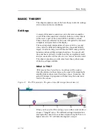
What is TVG?

TVG

means

Time Varied Gain

. As echoes will be weaker

when the distance to them increase, the sonar will automatically
amplify distant echoes more than close echoes. In practice, the
gain will increase in proportion with how long the sonar must
wait for the echoes.

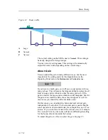
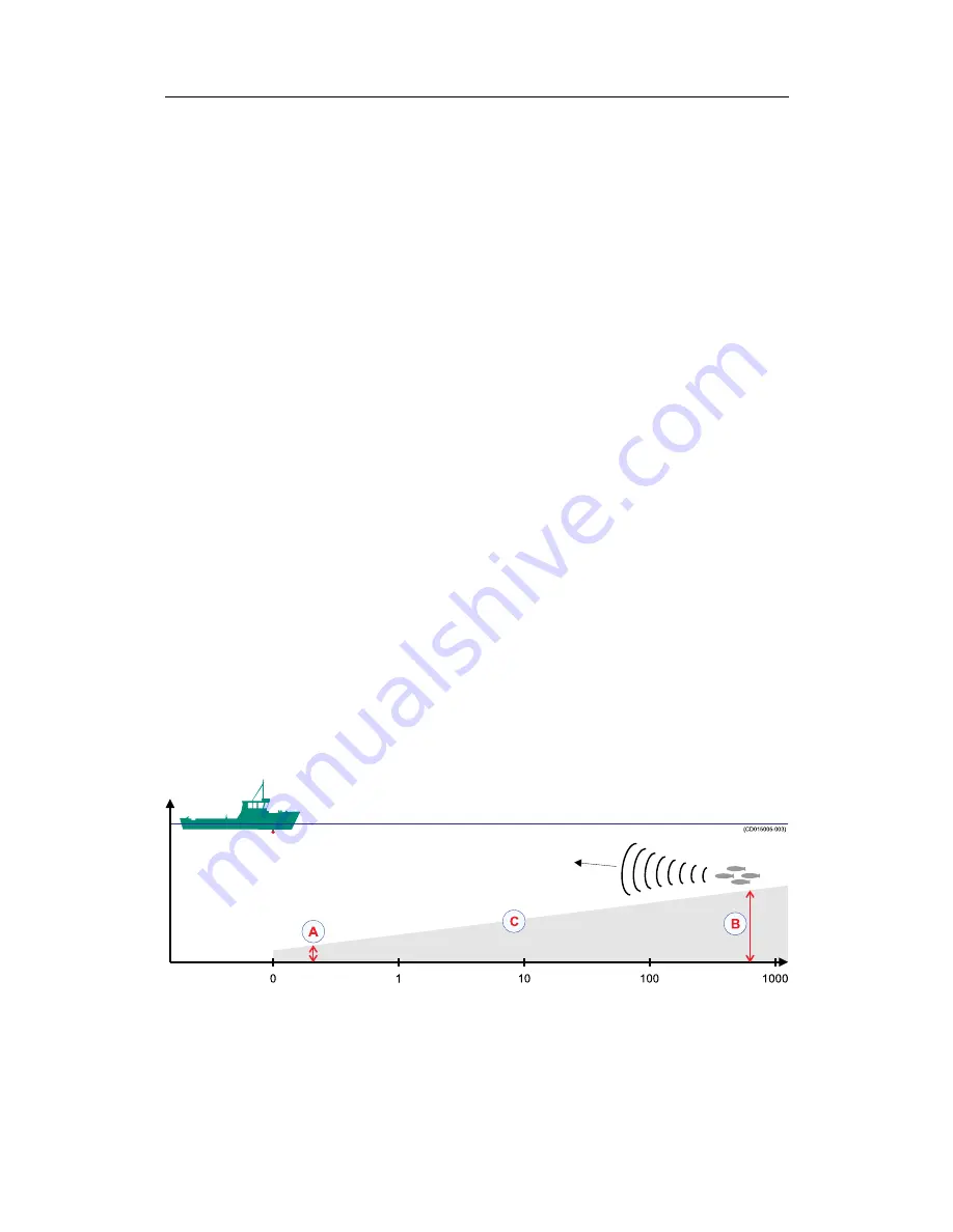
Figure 13

The TVG principle: The gain at time (B) is larger than at time (A)

A

(CD015005-003)

0

1

10

100

1000

B

C

When you choose the TVG setting you can either switch it off, or
choose a

“X log R”

value. The different settings determine how

much gain the sonar will use as time elapses along the X-axis. A
higher value for “X” will make the angle (C) steeper.

323773/C

67

Summary of Contents for SH90 - REV A

Page 1: ...Operator manual Simrad SH90 Fish finding sonar T E C H N O L O G Y F O R S U S T A I N A B L E F I S H E R I E S www simrad com ...

Page 2: ......

Page 3: ...nctionality including menus and all parameters refer to the Simrad SH90 Reference manual WARNING The Simrad SH90 sonar must never be powered up when the ship is in dry dock The transducer will be damaged if it transmits in open air To prevent inadvertent use of the sonar pull out the mains plug on the Processor Unit whenever the vessel is in dry dock 323773 C 20 08 2010 ...

Page 4: ...does not accept liability for any errors or omissions Warning The equipment to which this manual applies must only be used for the purpose for which it was designed Improper use or maintenance may cause damage to the equipment and or injury to personnel The user must be familiar with the contents of the appropriate manuals before attempting to install operate or work on the equipment Kongsberg Mar...

Page 5: ... on the display 18 Moving the boundary lines 19 Cosmetics 19 On line help 22 OPERATIONAL PROCEDURES 24 Menu procedures 24 How to hide the menu 24 How to simplify the menu 24 Gain adjustment procedures 25 How to adjust the gain 25 How to adjust the AGC 25 How to adjust the RCG 26 How to adjust the TVG 26 How to adjust the display gain 27 Mode procedures 27 How to select operational mode 27 How to d...

Page 6: ...How to add a target tracking line 40 User setting procedures 40 How to save the current user setting 40 How to load a user setting 41 How to rename a user setting 41 How to delete a user setting 41 How to load the factory settings 42 Installation of options 42 How to access the Install Options dialog 42 Install Options parameter dialog 43 Adding optional functionality 43 Software procedures 43 Bac...

Page 7: ... 67 What is TVG 67 What is AGC 68 What is the PP Filter 68 About pulse form and length 68 About beam widths 68 About Gain 69 What is RCG 70 About tilt 70 Noise and reverberation 71 Cavitation 71 Reverberation 72 Blocking 73 Check the noise yourself 73 Layers and deflections 74 Temperature and salinity layers 74 Deflections 75 323773 C 5 ...

Page 8: ...Simrad SH90 6 323773 C ...

Page 9: ...tudy the other documents that are provided with your system For detailed descriptions of all functions and parameters refer to the Simrad SH90 Reference manual References The following user manuals have been provided for the Simrad SH90 English manuals are provided with the SH90 when it is shipped When available manuals in other languages may be downloaded from http www simrad com Simrad SH90 Inst...

Page 10: ...sive repair is required When you dock the vessel It is very important that the sonar system remains switched off when the vessel is in dry dock If the transducer is subjected to transmit power when it is in open air it will be damaged As a safeguarding measure you can remove the power fuses on the sonar system before the vessel is docked As an extra safeguarding measure the sonar is by default pow...

Page 11: ...A stabilising system is included for electronic pitch and roll compensation Great emphasis has been placed on giving the best possible presentations on a high resolution colour display The SH90 Processor Unit is controlled by Microsoft s Windows XP operating system which result in a flexible choice of display modes for a large range of user applications The signal processing and beamforming is per...

Page 12: ...el Figure 1 Operating Panel A Main switch Power the sonar on and off lower and hoist the transducer B Symbol Control the target markers providing exact latitude and longitude positioning C Mode Select your favourite display mode or user setting with the push on a button D Gain Separate gain control for horizontal and vertical sonar presentation E Range Separate range control for horizontal and ver...

Page 13: ... button on the Operating Panel and keep it depressed for approximately two seconds POWER The green lamp on the right side of the button will flash to indicated that the power has been switched on and that the computer is starting up After a short period you will see the sonar picture on the display If the sonar system has been disconnected from AC power the Processor Unit must be started manually ...

Page 14: ...orizontal menu you will see that the TX power button flashes to remind you of this 5 Click the TX power to select Full How to switch off the sonar This procedure explains how to power off the Simrad SH90 1 Press the Up button on the Operating Panel Up The green lamp next to the button will flash and an audible signal indicates that the transducer is hoisted When the upper position has been reached...

Page 15: ...it If mains power is lost you can also use the hand crank provided How to perform basic operations Observe this brief procedure to familiarize yourself with the basic operations with echo presentations and menu operations Echo presentation and menu 1 Once the sonar system is up and running observe the layout of the display presentation On the right side observe the menu system A On the left side o...

Page 16: ...he cursor over to the left or right side of the display 5 Observe that the menu reappears on the selected side and that the remaining echo presentation area is not re scaled 6 Move the cursor towards the centre of the display and observe that the temporary menu disappears 7 On the Operating Panel press the Menu button one more time and observe that the menu reappears 14 323773 C ...

Page 17: ...ck on a button to change the applicable parameter If you click on the middle of the button you will normally open a dedicated parameter dialog for parameter selection If you click on the right or left side of the button you can scroll through the available choices F Parameter dialog When you click a button the relevant parameter dialog opens at the bottom of the menu Each parameter dialog holds on...

Page 18: ...ve three functions You can select a lower parameter value You can select a higher parameter value You can open the applicable parameter dialog C D015010A B A C A Click here to decrease the parameter value B Click here to increase the parameter value C Click here to open the parameter dialog Use the trackball on the Operating Panel and position the cursor over the left side of the button A Observe ...

Page 19: ...15010C B C D A 1 Move the cursor to the middle of the menu button A Observe that the cursor changes its shape to a menu symbol 2 Press the Select button on the Operating Panel 3 Observe that the corresponding parameter dialog B opens at the bottom of the menu 4 Move the cursor down to the dialog position the cursor over the requested parameter value C and press the Select button again 5 Observe th...

Page 20: ...H90 sonar all parameters are stored This function will cause the sonar to remember all the selected parameter settings even when the sonar is switched off Visual aids The sonar display contains not only the sonar picture and the menu system but also other information that is useful for efficient operation Common information on the display In nearly all display modes the following information is pr...

Page 21: ...Select button depressed Observe that the boundary line is moved 4 Release the Select button 5 Observe that the boundary line has been relocated to the new cursor position Cosmetics The choices in the Cosmetics menu allows you to enable or disable a range of visual aids in the sonar picture 1 Click the Display tab to open the Display menu 2 Click the Cosmetics button to open the Cosmetics menu 3 Ob...

Page 22: ...iew The Wind Marker B is shown as an arrow drawn from the Compass card pointing towards the centre of the display If a wind sensor is connected to the sonar it will automatically show the current wind direction Otherwise the wind direction may be entered manually The arrow has a fixed length it is not scaled according to the current wind speed The Distance Rings C are shown as dotted rings each wi...

Page 23: ...nge marker radius will be locked to the new position The Compass Card E is shown as short yellow lines for every 10th degree along the outermost circle of the sonar view A triangle symbol indicates each 90th degree It has labels indicating North East South and West It is updated when the heading of own ship has changed more than 1 degree The Vertical Ring F shows the selected range of the vertical...

Page 24: ...a comprehensive on line help system Help is provided in two levels On line and Free It is available from all the parameter dialogs and menus by clicking the Help button Once pressed the first help text will appear in the bottom of the menu This is the On line text It is short context sensitive and designed not to interrupt the operation of the sonar To close the Help parameter dialog click the Clo...

Page 25: ...oughout the document Click Free in the bottom left corner to return to the small on line parameter dialog or Close to exit the interactive manual Note If you click Close button to close the large interactive manual Free this manual will automatically reappear the next time you click a Help button 323773 C 23 ...

Page 26: ...e to remove the menu and one more time to retrieve it Alternative method 1 Click the Display tab on the sonar menu 2 Click the Full screen On button How to recall the menu 1 Move the cursor to the far left or far right side of the display 2 Observe that the menu system appears It can be shown on either side and will not affect the sonar picture 3 Open the Display menu and click Full screen Off How...

Page 27: ...n in the vertical presentation Gain V Gain V Alternative method 1 In the sonar s menu system click the Gain button on the Horizontal or Vertical menus to adjust the gain Click the left or right side of the Gain button to decrease or increase the gain or the middle of the button to open the parameter dialog For more information about this parameter see About Gain on page 69 How to adjust the AGC Th...

Page 28: ...if you wish to find scattered schools 1 Click the Horizontal or Vertical tab to open the respective menu 2 Click the RCG button to adjust the parameter Click the left or right side of the RCG button to decrease or increase the setting or the middle of the button to open the parameter dialog For more information about this parameter see What is RCG on page 70 How to adjust the TVG The TVG Time Vari...

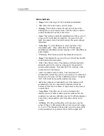
Page 29: ...button to decrease or increase the setting or the middle of the button to open the parameter dialog Mode procedures This section explains how to choose operational modes and how to set up the Mode buttons on the SH90 Operating Unit The various modes are described in chapter Display modes on page 52 How to select operational mode Your SH90 sonar is equipped with several operational modes Observe th...

Page 30: ...The top four modes on your list can be chosen by pressing the four Mode buttons on the Operating Panel 1 Click the Setup tab to open the Setup menu 2 Click the Sort Modes button to open the Sort Modes menu The Sort Modes menu lists all the available modes in their current order 3 Click one of the operational modes Observe that the Move down and or Move up buttons at the bottom of the menu are acti...

Page 31: ...r manual target tracking as the system is designed to calculate the speed course and distance between the last two chosen targets These target marker data are displayed in white figures for 15 minutes in the lower right hand corner of the horizontal presentation This function is also an effective method for determining the distance between two selected points on the screen About Circle markers Thi...

Page 32: ...n the ship s course line indicate the shooting one half and the end of the seine positions Three different nets can be defined if you click Gear on the Setup menu 3 Press the Gear button to delete the purse seine circle How to use the trawl symbol This is a useful aid in providing an overview of the trawl operation Trawl data can be set manually using the menu or automatically by interfacing a Sim...

Page 33: ...ted The Objects menu is shown in all display modes and displays the range R bearing B and depth D to all selected objects The identification ID abbreviations for the different objects are AT Automatic target track marker Ci Circle marker M Target marker OS Own Ship marker PT Position track marker F Radio buoy marker The number behind the ID abbreviation refers to the same number on the object in t...

Page 34: ...es Note that the Record button on the Operating Panel can be pressed at any time to start recording It is not necessary to open the Store Recall menu first When this button is used the currently selected recording mode will be used Prepare the recording parameters 1 Click the Setup tab to open the menu 2 Click the Store Recall button to open the Store Recall menu 3 Click the Store mode button to c...

Page 35: ...t recording A Click the Store button or B Press the Record button on the Operating Panel 2 Observe that the message field below the menu displays the image file names on a green background 3 To stop recording A Click the Store button or B Press the Record button on the Operating Panel How to recall sonar images Observe the following procedure to recall sonar images Preparations 1 Click the Setup t...

Page 36: ...ly resume normal operation How to keep sonar images When you store new sonar images they will by default be added to the list of Temporary files This list will contain maximum 100 images and when this limit has been reached the oldest files will be automatically removed 1 Click the Setup tab to open the menu 2 Click the Store Recall button to open the Store Recall menu 3 Observe the list of images...

Page 37: ... on screen keyboard opens to allow you to enter characters 6 Place the cursor at the beginning of the current file name and click the Del Delete button on the on line keyboard to remove the characters in the current file name Make sure that you do not delete the file name extension bmp 7 Click the necessary characters on the on line keyboard to build a new file name 8 Click the Close button in the...

Page 38: ...n the help window opens you can also access the Taskbar with the Start button 1 Insert a blank recordable CD in the Processor Unit 2 Observe that the operating system s auto start function opens a dialogue requesting guidance 3 Select Open writable CD folder using Windows Explorer and click OK 4 Observe that a Windows Explorer window opens 5 By means of normal Windows functions navigate to the fol...

Page 39: ...creendumps 6 Double click to open sub folder Permanent or Temporary 7 Click to select the images you wish to copy to the USB memory stick and copy them to the USB s Windows Explorer window 8 Remove the USB memory stick and close the Windows Explorer window To access the operating system functions you can click any Help button When the help window opens you can also access the Taskbar with the Star...

Page 40: ...the search program press the Manual button How to start the vertical search program Observe the following procedure to run the automatic search program Procedure 1 Press the Auto button in the Tilt field on the Operating Panel to start the vertical search program Auto 2 Hold the Auto button depressed while you also press one of the two arrow buttons in the Tilt field 3 Observe that the vertical op...

Page 41: ...edure to initiate a target track 1 Place the cursor over the desired target 2 Press the Target track button in the Train field on the Operating Panel A circle with dedicated identification A will appear on the display and its position will automatically be tracked by the system using the strongest echo centred in the track window B represented by the two bars on the audio line The size of the trac...

Page 42: ...w button in the Cursor field on the Operating Panel 4 Observe that a short cut menu appears on the display 5 Click View Menu and observe that the GeoView menu opens 6 Click the Target track button on the GeoView menu 7 Observe that the Target track parameter dialog opens below the menu 8 Choose the length of the tracking line and click Close to exit User setting procedures This section explains ho...

Page 43: ...p tab to open the menu 2 Click the User setting button to open the parameter dialog 3 Click the one of the user settings on the list to select it 4 Click the Rename button Observe that a parameter dialog opens to present the current name Observe that an on line keyboard opens to allow you to enter characters 5 Place the cursor at the beginning of the current name and click the Del Delete button on...

Page 44: ...stallation of options Optional functionality may be added to the SH90 All options are pre programmed into the standard sonar version When ordering a permanent option installation a code word will be released from Simrad For installation of options observe the following procedures How to access the Install Options dialog 1 Select the Setup menu 2 Click the Test button to open the System test menu 3...

Page 45: ...the Install Options parameter dialog and write down the HWID number 2 Send the HWID number to your dealer Makes sure that you write down the character string correctly 3 Use the sonar without the option until your dealer approaches you with a code word 2 Open the Install Options parameter dialog and click the Add License String number 3 Place the cursor in the text field 4 Type the code word on th...

Page 46: ... the Norton Ghost 8 utility on page 44 How to create a backup image using the Norton Ghost 8 utility This procedure is used when you wish to create a backup containing your entire SH90 Processor Unit The application used to do the backup is Norton Ghost 8 This application is provided on a bootable USB memory device To create the backup image you need the bootable USB memory device provided with th...

Page 47: ...th the image file creation 10 Wait for the backup process to finish Once completed remove the USB memory stick and restart the computer How to restore from a backup image using the Norton Ghost 8 utility This procedure is used when you wish to restore the SH90 software from a pre made backup file containing your entire installation The backup file may either be generic or it may be custom made to ...

Page 48: ... is the largest drive 6 Click Ok to verify the drive details 7 Click Yes to proceed with the restore 8 Wait for the restore process to finish This will take some time depending on the size of the data 9 Click Reset computer when the restore has finished 10 Allow Windows to boot 11 Click Yes when the computer wishes to restart 12 When the computer has restarted proceed with normal operation How to ...

Page 49: ... com Note This procedure is only valid for Windows XP 1 Connect a computer keyboard to one of the USB connectors on the computer 2 Allow the computer to restart with the new operating system 3 Answer Yes to reactivate Windows If the system fails to ask you can start the activation wizard by clicking Run in the bottom left corner and choose Activate Windows from the menu 4 Observe the following dia...

Page 50: ...Product key 9 Observe the following dialog 10 Enter the license code The license is found on a sticker on the rear side of the lid covering the DVD player 11 Click Update 12 Click Back 13 Observe the following dialog 48 323773 C ...

Page 51: ... to the Internet for longer than absolutely required It is neither protected by anti virus applications nor firewall 1 Click Yes let s activate Windows over the Internet now 2 Click Next 3 Observe the following dialog 4 Click No I don t want to register now 5 Click Next 6 Observe the following dialog 323773 C 49 ...

Page 52: ...telephone a customer service representative 2 Click Next 3 Observe the following dialog 4 Select your location 5 Call the number provided 6 Provide the installation ID to the service desk 7 Type in the confirmation ID provided to you 8 Click Next 9 Observe the following dialog 50 323773 C ...

Page 53: ...Operational procedures 16 When activation succeeds click OK and allow the computer to restart 323773 C 51 ...

Page 54: ... time this mode is especially useful for detection of weak echoes mixed with reverberation or noise The information recorded by the audio channel is always stored in the computer even if another mode is selected That means that this recording will always be presented when selecting the Bow up Audio mode Note that the vessel symbol can be moved to any position in the horizontal view with the cursor...

Page 55: ...raphical position where the vessel moves around the screen according to its present course and speed All echoes are always presented in their correct position relative to the vessel and their movements on the screen will be a true representation of the movements of the targets through the water When the vessel symbol reaches the edge of the screen it will automatically be moved back to the centre ...

Page 56: ...cribed but the two sonars are presented next to each other All settings can still be set individually for each of the two presentations 270 Vertical The 270 Vertical mode is specially designed for purse seining The vertical half slice is displayed in the lower left corner for normal setting with the net on the starboard side If the net is set on the port side the 60 degrees vertical slice will be ...

Page 57: ...bol The two markers will be placed at the cursor s location when you press the button The Own ship symbol produces a square symbol on the screen at the vessel s current location when the button is pressed while the Gear symbol is used to deploy a seine or trawl symbol See Markers and symbols procedures on page 28 Mode These four buttons provide fast access to the four operational modes you select ...

Page 58: ...r beam up or down You can also start an automatic tilt program to carry out automatic searches see How to start the vertical search program on page 38 Train These buttons control the sideways movements training of the sonar beam You can also start an automatic training program to carry out automatic searches and you can lock the beam on a chosen target or position See How to start the horizontal s...

Page 59: ...tive menus The active menus are those relevant for the different operational modes The menus are shown with vertical selector tabs on the right hand side and each menu can easily be selected using the trackball and the Select button on the Operating Panel All menus have access to on line help through a Help button Horizontal menu Menu description The Horizontal menu is used to control the horizont...

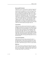
Page 60: ...automatically adjust the gain in the sonar to compensate for geometric spread and absorption Note that the TVG will only work within the first 1000 meters AGC Automatic Gain Control This function will automatically reduce the gain if you experience reverberation and noise or increase it if the conditions permit it Using the AGC will ensure best possible signal processing RCG Reverberation Controll...

Page 61: ... presentation If you activate the AGC Automatic Gain Control function this gain setting is influenced Pulse Form Use this function to select the form of the transmitted pulse This could either be FM Frequency modulation with different pulse lengths or CW with different pulse lengths TX Power This button controls the transmission power TVG Time Varied Gain This function will automatically adjust th...

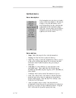
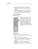
Page 62: ...s independent of the horizontal settings When any vertical setting is selected and defined in one mode the setting will be applied to all vertical modes The Tip button is only available on this menu The Tip button is used to tip the vertical slice to avoid the blind zone Menu buttons Range Select the range for the vertical presentation Tip Use this setting to tip the vertical slice to avoid the bl...

Page 63: ...move unwanted reverberation from the bottom or from the sea surface It may however also remove scattered fish PP Filter The Ping to Ping filter will only show you the echoes if they are still present after several consecutive pings 2 4 or 8 This function will provide you with a more stable echo presentation as spurious echoes will be suppressed Display menu Menu description The Display menu is sho...

Page 64: ... Backlight This function controls the intensity of the backlight in the Operating Panel Mode buttons Use this button to choose how the Mode buttons on the Operating Panel shall work You can either choose between the four most frequent modes or the four most frequent user settings Language Choose the menu language Units Allows you to choose the units used by the sonar Cosmetics Click to access the ...

Page 65: ...t documented Gear This button is used to select the type of fishing gear you use and to get the right size and position of the gear on the display School This parameter is used to obtain information of the volume estimation of a school in the automatic target tracking program Dead Reckoning This is an on off function When off the GPS is used to calculate the position of your vessel When on the cur...

Page 66: ...to be used when the sonar is used for scientific purposes When enabled the sonar will provide special information on an ethernet port This button replaces the Wind speed button Sort modes Click to access the Sort Modes temporary menu This menu is used to select the display modes to be activated by the four Mode buttons on the Operating Panel The four upper display modes in the Sort Modes menu will...

Page 67: ... be selected by the trackball and the Select button The temporary menus must however be removed manually using the Close button in the bottom of menu All temporary menus have access to on line help through a Help button Cosmetics menu The Cosmetics menu is activated by pressing the Cosmetics button in the Display menu The menu provides access to various parameters controlling the appearance of the...

Page 68: ...uration Sort Modes menu This menu is used to select the display modes to be activated by the four Mode buttons on the Operating Panel The four upper display modes in this menu will always be the modes selected by the four Mode buttons in the order they are sorted In order to sort the modes click on a mode to select it and click the Move Up and Move Down buttons to move the selected mode up or down...

Page 69: ... can also tilt the sonar beam vertically in order to achieve an optimum result and you can use the vertical slice to view across into the water This chapter provides you with some basic theory about some of the key settings available What is TVG TVG means Time Varied Gain As echoes will be weaker when the distance to them increase the sonar will automatically amplify distant echoes more than close...

Page 70: ...lated which means that the frequency of the transmitted pulse is changed during the transmission In most cases this method will provide better echo presentation and stability and you will avoid excessive noise and reverberation CW means continuous wave which means that the transmission frequency is fixed during the entire pulse When you use CW transmission you can choose the length of the pulses I...

Page 71: ... echoes This is because the large amplification presents all kind of noise and reverberation that the sonar picks up If the gain is smaller the noise and reverberation will disappear but if it the gain is too small the fish echoes may disappear as well In most cases you should try with a medium value On this sonar you can adjust the horizontal and vertical gain independent of each other The horizo...

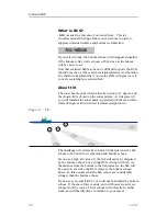
Page 72: ...icture At 0 degrees tilt you will transmit the sonar beam in parallel with the sea surface while 60 degrees tilt will direct it almost straight down Figure 15 Tilt CD015005D C B A The challenge will always be to find a tilt that prevents the fish echoes to be buried in reverberation and bottom echoes If you use a high tilt value A the fish will easily be disguised by the bottom echoes but a strong...

Page 73: ...enerated by the vessel engine propellers winches refrigerating plants etc Reverberation is caused by natural conditions in the sea temperature salinity sea state and bottom conditions The most common cause of acoustic noise is the propeller and the cavitation caused by its rotation Other typical noise sources on board your vessels are winches refrigerating plants power generators pumps and cranes ...

Page 74: ...commonly seen as a red stripe of echoes behind the vessel If you have big problems with cavitation try to adjust the propeller pitch and or the number of revolutions Reverberation Reverberation is generated when the echoes from your sonar transmission are reflected not only by fish and objects in the water but also from the bottom and the sea surface Figure 17 Reverberation CD015005E B A 1 Photo f...

Page 75: ...ially in higher sea states cause air bubbles to be generated and these bubbles will move along the hull This is called blocking In order to prevent this noise from disturbing your sonar operations it is important to lower the sonar transducer as far down below the hull as possible Check the noise yourself If you are bothered with acoustic or electric noise you can easily run a few simple tests to ...

Page 76: ...deflections Your sonar operations may also be disturbed by environmental situations that you are unable to control Two typical conditions are temperature and salinity layers and deflections caused by increasing or decreasing water temperature Temperature and salinity layers You may experience that temperature and or salinity layers exist in the water column Since the speed of sound in water depend...

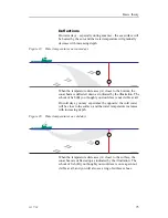
Page 77: ...illustration The school of fish B you thought you would see is not visible at all On cold days you may experience the opposite the cold water will be close to the surface and the water temperature increases with increasing depth Figure 20 Water temperatures on cold days CD015005H B A When the temperature decreases A closer to the surface the sonar beam is deflected up as indicated by the illustrat...

Page 78: ... on CD sonar images 36 Button menu basic operation 16 C Cavitation theory 71 Ci Circle marker 65 Circle marker 65 marker investigate 31 marker delete 32 Circle marker about 29 add 29 Colour Threshold menu button 62 Colours menu button 62 Compass Card description 21 Copy to USB sonar images 36 Cosmetics descriptions 19 menu 65 menu button 62 Cursor control basic operation 16 D Dead Reckoning menu b...

Page 79: ...off SH90 12 power on SH90 11 print sonar images 35 reactivate Windows XP license 46 recall sonar images 33 rename sonar images 35 rename user setting 41 restore from image media 45 restore from software backup 45 retrieve menu 24 retrieve the menu 13 save user setting 40 select mode 27 simplify menu 24 sort modes 28 store sonar images 32 target track 39 tracking line 40 track position 39 target 39...

Page 80: ...ff procedure 12 On procedure 11 On line help about 22 Free mode 22 On line mode 22 Operating panel description 55 Operating system reactivate Windows XP license 46 Operation basic 13 Operational modes 52 OS Own Ship marker 65 Own ship marker investigate 31 marker delete 32 Own Ship marker 65 Own ship symbol add 29 P Palette menu button 61 Panel Backlight menu button 62 Pictures burn on CD 36 copy ...

Page 81: ... images 35 user setting 41 Resolution menu button 62 Restore software 45 Reverberation theory 71 72 Reverberation Controlled Gain adjust 26 S Salinity layers theory 74 Save user setting 40 School menu button 63 Scientific Output menu button 64 Search program horizontal 37 vertical 38 Seine circle use 30 Select operational mode 27 Setup menu 63 Simrad SH90 familiarization 8 introduction 8 Software ...

Page 82: ...tton 62 User setting delete 41 load 41 menu button 64 rename 41 save 40 V Variable Range Marker description 21 Vertical menu 59 search program 38 Vertical 180 menu 60 Vertical Ring description 21 Vessel symbol add 29 VRM description 21 W What is AGC 68 beam width 68 blocking 73 cavitation 71 gain 69 PP Filter 68 pulse form 68 pulse length 68 RCG 70 reverberation 72 tilt 70 TVG 67 Wind direction me...

Page 83: ...Index 323773 C 81 ...

Page 84: ...aritime AS Kon g s b e rg M a rit im e A S S t ra n d p rom e n a d e n 5 0 P O Box 1 1 1 N 3 1 9 1 H ort e n N orwa y S im r a d Te le p h on e 4 7 3 3 0 3 4 0 0 0 Te le fa x 4 7 3 3 0 4 2 9 8 7 con t a ct s im ra d com w w w s im r a d c o m ...

Page 85: ......
Page 86: ...Simrad SH90 Fish finding sonar Installation manual Simrad SH90 Fish finding sonar Installation manual Simrad SH90 Fish finding sonar Installation manual ...

Reviews: