


Controller Set Up-
11
IV-B. SETUP
Startup Screen
Setup Menu
System Setup
Controller Setup
After the AFC panel has been wired completely
and all connections confirmed, flip the
Control
Power
switch to
ON
to apply power to the panel.
On first power up the touch screen will be mostly
blank as seen on
Startup Screen
.
Below the
screen are 5 function keys used in
conjunction with the information on the screen.
On the
Startup Screen
,
the screen shows
SETUP
above the "F1" function key. In this
instance, the "F1" function key would take you to
the setup menu.
From the setup screen you may choose to
configure the
MODBUS
setting,
SYSTEM
settings, or enter the
TANK SETUP
by pressing
the soft keys on the touch screen. (See
Setup
Menu
)
Please refer to Appendix B for 7 inch touch screen
examples.
System Setup
If
MBV
s are installed, you may enter the delay
time in seconds for the valve fail timer. You may
also select to display the tank level in either
GALLONS
or
LITERS
. Tank level in percent will
always be displayed regardless if gallons or liters
is selected.
(See
System Setup
)
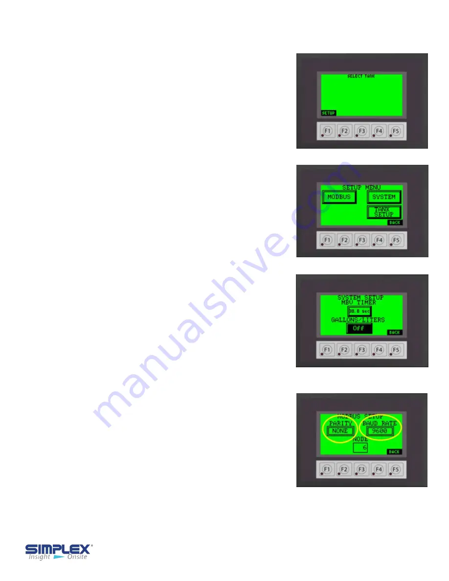
Modbus Setup
Each unit is capable of modbus communication via
RS485
. You may choose the
PARITY
,
BAUD
RATE
, and
NODE
address for the unit. The
following information is preset from the factory and
may NOT be changed via the touch screen.
PROTOCOL
: Modbus
HEX
ECHO
: 2-Wire
STOP BITS
: 1
Please refer to the Wiring Diagram in the provided
drawing packet for field communication connections.
For
TCP/IP
or
Bacnet
communication settings, please see the
MODBUS POINTS
LIST
in the drawing packet shipped with the unit.
Modbus Settings


