background image

2

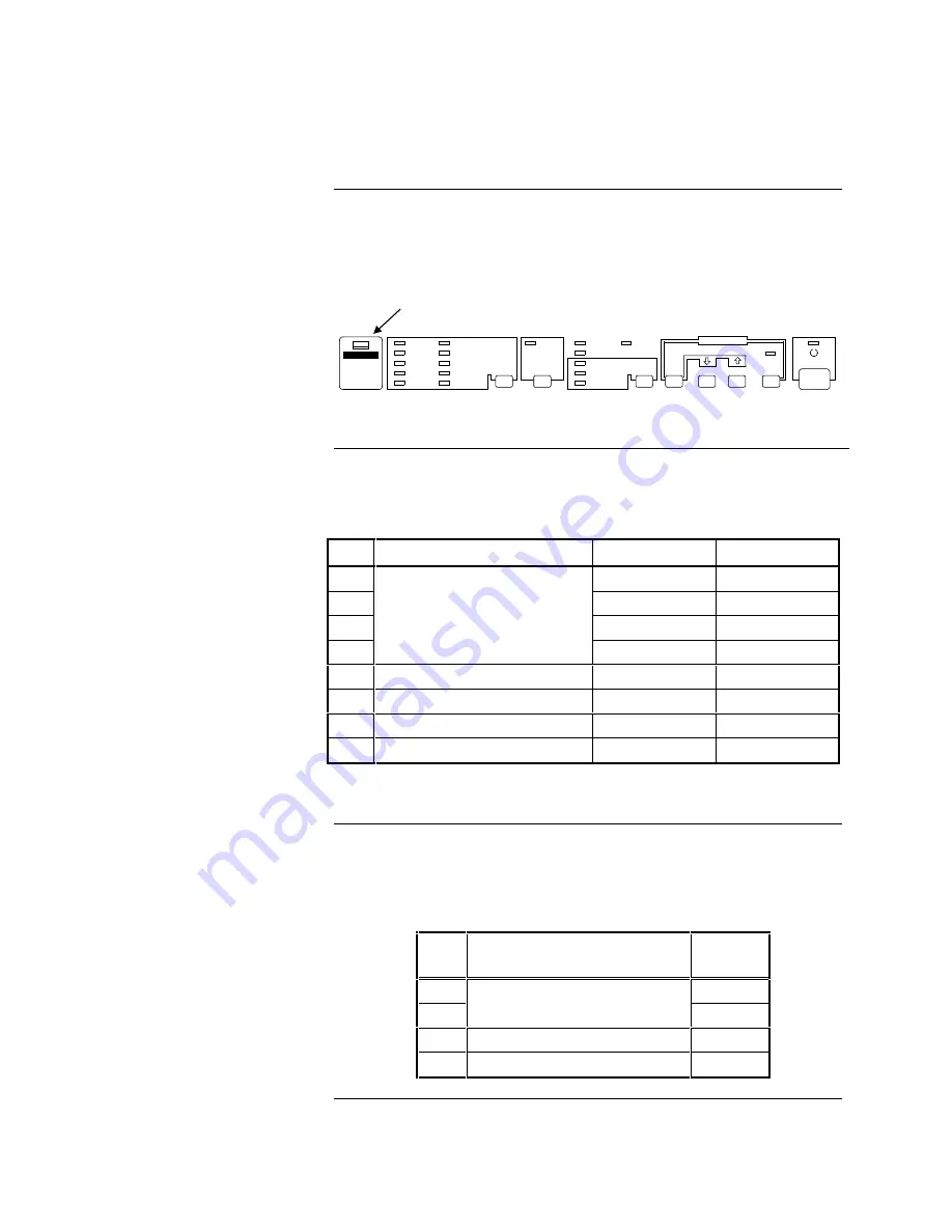
The 4190-9007 printer is equipped with two DIP switches that control the
printer’s features.  The DIP switches are located behind the switch cover on the
control panel (see Figure 1).  Tables 1 and 2 define the settings for DIP Switch 1
and 2.

DRAFT

COURIER

ROMAN

SANS SERIF

PRESTIGE

SCRIPT

SCRIPT C

OPERATOR

OPERATOR-S

OCR-B

FONT

CONDENSED

MULTI-PART

PAPER-OUT

BIN 1

BIN 2

TEAR OFF

DATA

FONT

FONT

BUFFER CLEAR

LOAD/EJECT

LF/LL

PAUSE

MICRO FEED

OPERATE

Figure 1.  Location of DIP Switch Cover

DIP Switch 1 has eight switches.  Table 1 describes the settings for DIP Switch 1.

Table 1.  DIP Switch 1

SW

Description

ON

OFF

1-1

ON*

1-2

ON*

1-3

ON*

1-4

USA

OFF*

1-5

Print Direction

Unidirectional

Bidirectional*

1-6

Printer Mode**

IBM emulation

ESC/P 2*

1-7

Input buffer

None

8KB*

1-8

1-inch skip-over-perforation

ON

OFF*

Notes: 

* Indicates Simplex settings.

** SW 1-6 functions only on the European version of this printer.

DIP Switch 2 has four switches.  Set these switches to the ON position.
Table 2 describes the settings for DIP Switch 2.

Table 2.  DIP Switch 2

SW

Description

Simplex

Setting

2-1

ON

2-2

Page length

(for continuous paper)

ON

2-3

Tear Off

ON

2-4

Auto line feed

ON

Control Panel DIP Switches

Overview

Setting DIP Switch 1

Setting DIP Switch 2

DIP switch cover

Summary of Contents for 4190-9007

Page 1: ...provide reasonable protection against harmful interference when the equipment is operated in a commercial environment This equipment generates uses and can radiate radio frequency energy and if not installed and used in accordance with the instruction manual may cause harmful interference to radio communications Operation of this equipment in a residential area may cause interference in which case...

Page 2: ...able 1 describes the settings for DIP Switch 1 Table 1 DIP Switch 1 SW Description ON OFF 1 1 ON 1 2 ON 1 3 ON 1 4 USA OFF 1 5 Print Direction Unidirectional Bidirectional 1 6 Printer Mode IBM emulation ESC P 2 1 7 Input buffer None 8KB 1 8 1 inch skip over perforation ON OFF Notes Indicates Simplex settings SW 1 6 functions only on the European version of this printer DIP Switch 2 has four switch...

Page 3: ...en after installing the interface card DIP Switch 2 is not readily accessible after installation Therefore make any necessary adjustments to DIP Switch 2 before installing the serial interface card This section describes the DIP switch settings for operation with compatible Fire Alarm systems Refer to the Serial Interface Card manual provided with the serial interface card for detailed information...

Page 4: ...C 4120 NPU OFF No parity 2120 4010 ON 1 4 Parity Check 2 ON For even parity 4020 4100 4120 OFF For odd or no parity 2120 4010 4120 GCC 4120 NPU ON 1 5 Baud Rate 1 ON for both 1200 baud 2120 4020 4100 4120 and 9600 baud 4010 4120 GCC 4120 NPU N A ON 1 6 Baud Rate 2 N A OFF for both 1200 baud 2120 4020 4100 4120 and for 9600 baud 4010 4120 GCC 4120 NPU OFF Note Units must be set for NO parity at 120...

Page 5: ... 4020 4100 4120 and 9600 baud 4010 4120 GCC 4120 NPU N A ON 2 2 Baud Rate 4 ON for 9600 baud rate 4010 4120 GCC 4120 NPU OFF for 1200 baud rate 2120 4020 4100 4120 OFF 2 3 Handshake DTR X on X off ON 2 4 RS 232D Current Loop RS 232D Current Loop ON Note Unit to be set for 1200 baud Serial Interface DIP Switches Continued Serial Interface Card DIP Switch 2 ...

Page 6: ...ce compartment is located directly above the parallel interface port on the rear panel of the printer see Figure 3 Note When connecting to a 4120 GCC system you have the option of using the parallel port If using this option refer to the section Parallel Interface Option with the 4120 GCC SERIAL INTERFACE COMPARTMENT RS 232 CONNECTOR WITH INTERNAL SUPPRESSION 733 937 HARNESS SUPPLIED PARALLEL INTE...

Page 7: ...URNISHED BLK GRN WHT Use the standard parallel cable supplied with the printer the 733 937 harness is not used with the parallel interface Follow these steps 1 Disable the serial interface as follows a Loosen the two screws that hold the serial interface card in place b Pull the card out of the unit 2 Connect the cable from the parallel port of the printer to the parallel port of the host system N...

Page 8: ...the connection to the 4010 FACP 3 7 20 TO 4190 9007 PRINTER 3 7 20 2 RED NOT USED RECEIVE COMMON HANDSHAKE 2120 BMUX RS 232 CONNECTOR 733 937 HARNESS FURNISHED BLK GRN WHT Figure 6 Connecting to 2120 Multiplex System 1 2 3 4 5 6 3 1 RED NOT USED GRN 7 20 TO 4190 9007 PRINTER 733 937 HARNESS FUNISHED WHT BLU Figure 7 Connecting to a 4010 FACP Connecting to Fire Alarm Systems Continued Connecting to...

Page 9: ...ess ENTER again to confirm that you want to add an RS 232 card A message appears indicating that the system is configuring the card Press the EXIT key once to move back one menu level and then continue below with Step 5 in the next section Use the following steps to configure the printer settings baud rate etc for the RS 232 port to which the printer is attached Before beginning ensure you know th...

Page 10: ...sed 80 column printer Unused PRT40S Supervised 40 column printer PRT40U Unsupervised 40 column printer PRT80S Supervised 80 column printer 9 Use the arrow keys to move the bracket to the BAUD Parameter Use the NEXT and PREVIOUS keys to select a choice for this parameter Choices are as follows 1200 2400 4800 9600 19200 38400 10 Use the arrow keys to move the bracket to the PARITY parameter Use the ...

Page 11: ...message appears indicating that the configuration has changed Move to the SAVE CFIG choice and press ENTER Another message appears asking you to confirm the Save operation Press ENTER to save the new CFIG Table 5 Routing Specific Events Prompt Default Setting Explanation Send Fire Events to Port Yes Routes information on all fire alarms to the printer Send Supervisory Events to Port Yes Routes inf...

Page 12: ...Note The 733 937 harness is not used when connecting to the 5001 Nurse Call system Figure 8 illustrates the connection between the 4190 9007 printer and the 5001 CPU 2 6 7 TO 4190 9007 PRINTER RED 3 6 7 1 SHIELD COMMON 5001 CPU DB25 SERIAL PRINTER PORT 1 5 WHT GRN BLK SHIELD RECEIVE 11 20 HAND SHAKE SEND DATA 5 CONDUCTOR CABLE W SHIELD 18 AWG MAXIMUM DISTANCE BEWEEN PRINTER AND 5001 CPU IS 100 FEE...

Page 13: ...el buttons Table 6 Using the Control Panel Buttons If you want to Then Temporarily stop printing Press the PAUSE button Resume printing Press PAUSE again Load paper manually single sheet or continuous Printer normally loads paper automatically Eject single sheet paper already in the loading position Feed continuous paper backward from the loading or tear off position to the standby position Press ...

Page 14: ...te Green Operate switch is on and power is supplied Printer is not ready to print data Pause Orange Operator has pressed PAUSE button to prevent printing Paper Out Red Printer is out of paper Consult printer manual for details on printer set up control logic and paper loading Control Panel Continued Control Panel Lights Additional Information ...

Reviews: