


_
µA=
B1
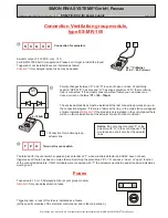
value to be measured:
0,8 - 1 mA (until date of manufacture 12/04, value 80 - 100 µA)
Button loop
27 k
V
*
Y
_
at least 21 V (Mains)
at least 18 V (Accu)
V=
OK
_
V=
21 V
3
OK
RA
Y
B1
M
-
RZ
Break glass button terminal
M
_
V=
at least 20 V (Mains)
at least 18 V (Accu)
Connection central relay module,
type ES-ZL-100
Installation manual ESM-T/X-EV (24 A / 48 A / 72 A)
Page 14/20
SIMON RWA SYSTEME GmbH, Passau
ESM-T/X-EV with power supply
Dublications, also in extracts, are only legal with express authorisation from SIMON RWA SYSTEME GmbH Passau
®
The minus potential of the minus clamp (-) is considered to be a basis for all
terminals for signalizing. The clamp “OK” supplies a plus potential at least 21 V
if there is no failure at the control unit (complete SHEV group). Between these
clamps hangs the green LED
of the main station. The clamp “OK” (Y”) is
fused by a PTC (approx. 100 mA - never connect more than 1 main station).
OK
“Y” provides a plus potential for failure indication. This signal is a permanent signal,
that is turned into a blink signal by an electronics at the main station’s circuit board.
Between these clamps hangs a yellow diode
of the main station for failure
indicating. Attention!! “Y” is supplied by emergency current.
“M” provides a plus potential at “SHEV OPEN” (HE, RM, TH,
BMZ). Between these clamps hangs the LED-indication
“triggering” of the stations (HE 075/076). These output is also
fused with a PTC and is able to supply max 8 OPEN-indications of the
stations in parallel. If more than 8 break glass buttons are connected the
output “M” breaks down to an undefinable value.
Never
connect more than one main and seven slave stations. If some
additional stations are required an auxiliary relay (HR-195) is necessary.
Attention!!
“B1” provides the plus potential for the closed current loop, wherewith the button lines of
the electrical break glass buttons are monitored. The current of this output is limited to 100
mA by a PTC. The
closed current tolerance lies between 50 µA and 5 mA.
If the closed
current value doesn’t lie within this range, the control unit will be triggering. The end
resistor has to be added to the button line at the last terminal (like shown in the diagrams).
If no buttons shall be connected the resistor needs to be installed directly into the control
unit (delivery state). This loop is monitored for failure and short circuit.
If the end
resistor stays in the control unit, triggering via the break glass button (HE 075/076) will be
not possible. Alarm will
not
be set.
Attention!!
* 270 k
12/04)
(until date of manufacture
When the potential of terminal “B1” is clamped onto the terminal RZ, this will cause a RESET of the system and
consequently a closing of the connected acutators. The plus potential of the terminals “B2” and “B3” thereby get
reseted (= smoke detector - reset). This function is clamped at the button CLOSE/RESET (terminals “8” and “9”) at
the main stations. The “Reset” - button in the control panel has the same function.
When a SHEV alarm
has been triggered all other functions are disabled, only by RESETTING other functions like wind and rain detector
or vent button will be reactivated. The terminal RA is not relevant at “normal” operation of the control unit.
Attention!!


