PAGE 32
TECHNICAL DESCRIPTION
The IXP controls an LXT971 PHY chip (U20) that provides a 10/100 Base-T Ethernet
interface. The PHY is connected to an RJ-45 socket with built-in magnetics; the socket
also presents two external LEDs which are configured to indicate activity and 10/100
status.
RS232 Serial Interface (DB-9)
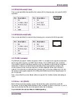
The rear of the Blade contains a standard 9-way Serial connection in order that a straight
through cable may be used to connect a PC to the IXP.
UART Serial Interfaces (Front Panel RJ-45)
The IXP presents a serial port interface to the RJ-45 port in the front panel.
4.2.2.6 CoDec
Audio received from either or both of the line ports and the PSTN interface is fed into a
chain of 3x AD73322L codecs (U52, U53 and U54) that is connected to the DSP via its
SPORT (Serial PORT) interface serial link.
The DSP performs audio signalling to the line equipment or patches the audio to the radio
module.
Handset audio is fed via a codec (U53) into the DSP allowing it to be mixed to line or the
radio modules under software control. Audio is also fed to the speaker on the front panel.
The codec contains built-in analogue gain adjustment under software control.
4.2.2.7 Audio Interface
General
External audio equipment is connected to either of the two independent audio ports which
are presented barriered on the RJ45 connectors, and un-barriered on the 37-way Facilities
Connector.
Two and Four Wire
The barriered connections are link selectable as either two or four wire. In two-wire mode
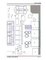
the balance of the hybrid can be set manually by moving LN18 (LN16 for port 2) to
position 2-3. If a test tone is generated to line, the reflected audio can be monitored on
TP57 (TP62 for port 2) and variable resistor R128 (R135 for port 2) can be adjusted to
give the minimum level.
At the time of configuration, the audio levels of the line ports must be set for optimal
performance. In line-to-air mode, it must be possible for a -10dBm signal to generate a
2.5kHz (full-scale) deviation. In loopback mode, an undistorted signal up to -10dBm should
be re-outputted with unity gain; this can be configured by inputting a -14.4dBm signal
(equivalent to 1.5kHz/60% deviation over air) into the line port and altering the gain level
until an equivalent -14.4dBm signal is seen at the output.
E & M
The control board contains opto-isolated digital inputs (U9, U14) and outputs (U8, U13). In
order to support local connections where an external bias voltage is not present, Fuse-
Summary of Contents for Xfin Blade
Page 10: ......
Page 22: ......
Page 35: ...XFIN BLADE SM TECHNICAL DESCRIPTION PAGE 35...
Page 50: ......
Page 58: ...PAGE 58 PRODUCT VARIANTS AND ACCESSORIES...
Page 64: ...PAGE 64 SPARES...
Page 72: ...PAGE 72 PROGRAMMER GUIDE...
Page 75: ...XFIN BLADE SM CONTROL CARD BLOCK DIAGRAM PAGE 75 B CONTROL CARD BLOCK DIAGRAM...
Page 76: ......


