background image

Assisting the automation

industry since 1986   

User manual

METER

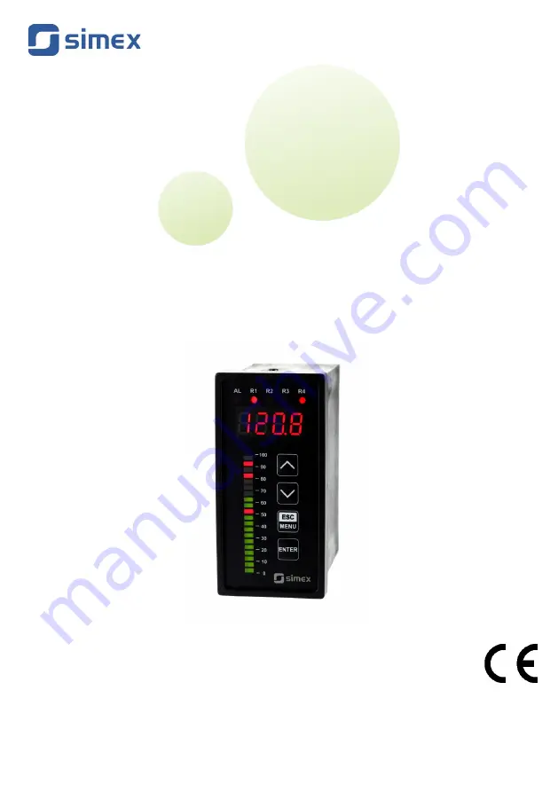
SUR-49B

Firmware: v.1.04 or higher

Input type: universal

Multicolour bargraph

Read the user's manual carefully before starting to use the unit or software. 

Producer reserves the right to implement changes without prior notice.

 2021.11.05

SUR-49B_INSSXEN_v.1.00.002 

Summary of Contents for SUR-49B

Page 1: ...SUR 49B Firmware v 1 04 or higher Input type universal Multicolour bargraph Read the user s manual carefully before starting to use the unit or software Producer reserves the right to implement chang...

Page 2: ...7 3 2 bEEP menu 32 7 3 3 inPt menu common parameters 32 7 3 4 inPt menu parameters of temperature inputs 33 7 3 5 inPt menu parameters of current and voltage inputs 33 7 3 6 OutP menu 35 7 3 7 bAr me...

Page 3: ...g to this manual local safety and EMC regulations If the device is equipped with PE connector it should be connected to PE wire Otherwise PE wire should be connected to GND connector The unit must be...

Page 4: ...r similar 2 GENERAL CHARACTERISTICS The SUR 49B meter is equipped with one current input 0 20mA two voltage inputs 0 10V and 0 150 mV one RTD input Pt 100 500 1000 and one TC input thermocouple K S J...

Page 5: ...it for 0 20 mA range Current input resistance 65 W typical 30 W Accepted prolonged input overload 20 Voltage input 10V range 0 5 V 1 5 V 0 10 V 2 10 V Voltage measurement accuracy 0 1 25 C one digit f...

Page 6: ...100 mA 50 mA 11 4V 15V AC DC Relay output 0 1 2 or 4 NO 5A 250V AC resistance 3A 250V AC reactance OC type output 0 or 1 30 mA 30V DC 100mW Active current output optional for two relays and one OC ty...

Page 7: ...mm Operating temperature depending on version 0 C to 50 C or 20 C to 50 C Storage temperature depending on version 10 C to 70 C or 20 C to 70 C Humidity Altitude 5 to 90 no condensation up to 2000 me...

Page 8: ...ported to the carrier Also write down the unit serial number located on the housing and report the damage to the manufacturer Attached with the unit please find user s manual warranty assembly bracket...

Page 9: ...User manual METER SUR 49B a b Figure 4 1 Mounting hole dimensions a recommended b allowable 9 43 mm 92 mm max 5 mm 43 mm 8 mm 13 mm 8 mm 13 mm 90 5 mm 1 mm 1 mm max 5 mm...

Page 10: ...er manual METER SUR 49B Figure 4 2 Installing of brackets and dimensions of connectors Figure 4 3 Minimum distances when assembly of a number of units 10 92 mm 5 mm 12 mm 10 mm 8 5 mm 16 mm 115 mm 67...

Page 11: ...order to secure against accidental short circuit the connection cables must be terminated with appropriate insulated cable tips Tighten the clamping screws The recommended tightening torque is 0 5 Nm...

Page 12: ...s recommended Twisted pair best if shielded must be used with RS 485 serial transmission connections In the case of measurement or control signals are longer than 30m or go outside of the building the...

Page 13: ...DATA Uo 24V 5 10 Imax 100mA 50mA R2 optional R1 optional n c n c n c n c 1 2 10 11 12 13 14 15 4 3 31 32 33 34 35 5 6 7 8 9 33 34 TC mA 31 34 RTD RTD V mV RS 485 DATA GND DATA Uo 24V 5 10 Imax 100mA...

Page 14: ...4 RTD RTD V mV RS 485 DATA GND DATA Uo 24V 5 10 Imax 100mA 50mA R1 optional n c n c OC3 Umax 30V DC Imax 30mA Pmax 100mW OC3 optional R2 optional depending on version Power supply 1 2 10 11 12 13 14 1...

Page 15: ...15 4 3 31 32 33 34 35 5 6 7 8 9 33 34 TC mA 31 34 RTD RTD V mV RS 485 DATA GND DATA Uo 24V 5 10 Imax 100mA 50mA R1 optional OC3 Umax 30V DC Imax 30mA Pmax 100mW OC3 optional R2 optional depending on v...

Page 16: ...easurement errors Measured value can be corrected constant correction using toFS parameter from menu inPt Due to low precision 2 wire connection is not recommended When 4 wires or 2 wires connection i...

Page 17: ...12 15V AC DC Figure 4 16 Connection of power supply and relays Contacts of relay outputs are not equipped with spark suppressors While use the relay outputs for switching of inductive loads coils cont...

Page 18: ...ion circuit connection a to relay terminals b to the inductive load Figure 4 18 Example of OC type outputs connection for device with OC type output only 18 N 10 11 10 11 L L N 5 6 12 13 voltage input...

Page 19: ...connection for device with passive current output only Figure 4 21 Example of active voltage outputs connection for device with active voltage output only 19 current input 0 20 mA Logic controller 3 4...

Page 20: ...e permanent damage to the housing Product marked with this symbol should not be placed in municipal waste Please check local regulations for disposal of electronic products 5 FRONT PANEL DESCRIPTION S...

Page 21: ...nge Figure 6 1 6 2 For temperature inputs TC and RTD there is linear characteristic available only For this kind of inputs nominal measurement range and permissible measurement range are the same no r...

Page 22: ...or the remote controller to do it Note all parameters can be remote changed via RS 485 interface Configuration of the device via menu or RS 485 interface does not stop measures 6 1 1 Detection OF THE...

Page 23: ...ding Displaying peak value is signalized by flashing most right decimal point The relays LEDs and analogue outputs can be controlled depend on the current value of input signal or the peak value see H...

Page 24: ...r two thresholds values If one threshold is used 6 5 the relay can be turned on modE on or off modE oFF when the input signal value is contained in zone A If two thresholds are used 6 6 the relay will...

Page 25: ...the border values see points A and C 6 7 a b c If values of t on or and toFF are positive then relay state will be turned on if the input value exceeds the border values and stay bigger or lower duri...

Page 26: ...xpected value allowed deviation BON BOFF CON COFF EON EOFF relays state changes moments for t on 0 toFF 0 tA tB tC tD tE time periods while input signal is in zone A or zone B Figure 6 8 Principle of...

Page 27: ...described in chapter 7 3 MENU DESCRIPTION Some of the parameters can be accessed without entering menu quick view mode After pressing or v button name of the threshold e g rEL1 and its value will be...

Page 28: ...e of current position flashing digit or the sign Short pressing of the ENTER button causes change of the position digit Press ENTER at least 2 seconds to accept the changes after that question SEt is...

Page 29: ...change of value acceleration deceleration direction change While editing switch parameter selection of switch parameter If numerical parameter is being edited a short press of ENTER button change edit...

Page 30: ...m value of relay hysteresis HYSt hysteresis of relay range 0 999 Full hysteresis of the relay is equal to 2 times HYSt parameter The relay state can change when an input signal is out of threshold hys...

Page 31: ...urn off delay time the relay is turned off with delay equal toFF if the input value exceeds appropriate border value defined with threshold and hysteresis at least toFF time toFF range 0 99 9 defined...

Page 32: ...signal r3 if this parameter is set to on activation of relay R3 causes by acoustic signal r4 if this parameter is set to on activation of relay R4 causes by acoustic signal Acoustic signal turned on...

Page 33: ...Sqr square Sqrt square root When one of those characteristics is chosen display range is defined by Lo C and Hi C USEr user defined characteristic Maximal length 20 points Every point is defined by u...

Page 34: ...prox 1 5 sec After that device waits for selection of point being deleted by v buttons The short pressing of ENTER button causes by switching between X and Y value of the displayed point The long pres...

Page 35: ...raph the procedure of the permissible input range determining is presented in details If the measurement value do not exceeds permissible measurement range but displayed value exceeds range 999 9999 t...

Page 36: ...e B higher range limit 20mA 5V 10V A lower range limit 0mA 4mA 0V 1V 2v OutL parameter can be greater than OutH In this case the conversion characteristic is reversed it means that if input value rais...

Page 37: ...1 2 voltage will be set to 1 2 V 0 6 voltage will be set to 0 6 V 0 0 voltage will be set to 0 V When the critical situation goes the output signal will be set to value calculated due to formulas give...

Page 38: ...critical situation will occur when particular relay will be opened The critical situation of the bargraph will occur in case when any of defined situation occur The critical situation of the bargraph...

Page 39: ...s rEAL current value is displayed HOLd peak drop value is displayed H r1 H r4 relay LED outputs R1 R4 operation mode rEAL relay LED operates depend on the current value HOLd relay LED operates depend...

Page 40: ...pter 11 1List of registers mbtO this parameter defines maximal time sec between following frames received by the device If the delay will be greater than the value of mbtO parameter the relays and ana...

Page 41: ...his setting allows to restore the factory settings of the device To get the access to this option special password is required 5465 next the device displays acknowledge question SEt Press ENTER to ack...

Page 42: ...menu ENTER MENU ESC Measurement mode ENTER MENU ESC ENTER MENU ESC rEL3 MENU ESC MENU ESC bEEP MENU ESC inPt MENU ESC AL r1 r2 r3 r4 Parameter edition ENTER MENU ESC ENTER ENTER MENU ESC tYPE CHAr FiL...

Page 43: ...ENTER MENU ESC ENTER ENTER MENU ESC Scod A r1 A r2 A r3 A r4 ENTER MENU ESC ENTER MENU ESC modE PEA timE Hdis H r1 H r2 H r3 H r4 Parameter edition HOUt See previous page MENU ESC SEt 4 digit special...

Page 44: ...r ranges and units The first step to compute the result of measure is the calculation of the normalized result it means result of 0 1 range To do it the begin of the input range 0 mA for 0 20mA range...

Page 45: ...r In such a case for an increasing value of input current the displayed value decreases Figure 10 1 Normal Lo C Hi C and inverted Lo C Hi C characteristic 10 1 2 Square characteristic The normalized r...

Page 46: ...normalized result In the device computes specific segment e g for characteristic from figure below and In 0 65 the segment between points X 50 0 and X 70 0 will be chosen Let s mark those points as P...

Page 47: ...mA 6 mA and this result should be divided by the width of input range 16 mA Finally the normalized result In 6 16 0 375 In case when input current exceeds nominal measurement range calculations are s...

Page 48: ...square characteristic 0 375 2 1200 300 211 and next the Lo C value is added to the result so the displayed value W 211 300 89 b Iin 2 5 mA and In 0 0938 W 287 c Iin 20 5 mA and In 1 0313 W 1295 Exampl...

Page 49: ...stic see page 46 X6 PL 30 Y6 PL 30 X7 PH 40 Y7 PH 80 and Ip 0 3 the displayed value W In I p Y PH Y PL X PH X PL 100 Y PL 0 375 0 3 80 30 40 30 100 30 67 b Iin 2 5 mA and In 0 0938 because of the norm...

Page 50: ...20 5 10 0 20 0 10 0 16 mA 4 mA 1 05 16 4 20 08 mA Calculated Iout do not exceeds the output working range 3 8 21 mA c D 30 0 According to formula from page 36 Iout 30 0 10 0 20 0 10 0 16 mA 4 mA 2 16...

Page 51: ...or of user characteristic 20h waiting for the first measure 03h Yes 0 3 Pnt parameter in InPt menu decimal point position 0 0 1 0 0 2 0 00 3 0 000 04h Yes see descr State of the relays and alarm LED b...

Page 52: ...ace 0 write denied 1 write allowed 24h Yes see descr Parameters of SECU menu binary format 0 oFF 1 on bit 0 A r1 parameter bit 1 A r2 parameter bit 2 A r3 parameter bit 3 A r4 parameter 25h Yes 0 5 rE...

Page 53: ...meter in rEL2 menu 0 seconds 1 minutes 3Eh Yes 0 2 AL parameter in rEL2 menu 0 no changes 1 on 2 off 3Fh Yes 999 9999 SEt2 parameter in rEL2 menu no decimal point included 40h Yes 999 9999 SEtP parame...

Page 54: ...ter in HOLd menu 0 rEAL mode 1 HOLd mode 58h Yes 0 1 HOUt parameter in HOLd menu 0 rEAL mode 1 HOLd mode 70h5 Yes 999 1999 The value of X coordinate of point no 1 of the user defined characteristic ex...

Page 55: ...eter P2AL of sub menu bAr critical situation defined for relay R2 0 no change 1 option morE 2 option LESS 3 option on 4 option oFF BAh Yes 0 4 Parameter P3AL of sub menu bAr critical situation defined...

Page 56: ...REG H L Starting address address of first register to read write Hi and Lo byte COUNT H L No of registers to read write Hi and Lo byte BYTE C Data byte count in answer frame DATA H L Data byte Hi and...

Page 57: ...nswer the same as the message ADDR FUNC REG H L DATA H L CRC L H 01 06 00 20 00 02 09 C1 4 Change of baud rate of all devices connected to the net BROADCAST message ADDR FUNC REG H L COUNT H L CRC L H...

Page 58: ...L H 01 03 06 00 0A 00 00 00 01 78 B4 DATA H1 L1 reg 01h 10 displayed value 1 0 DATA H2 L2 reg 02h 0 no errors DATA H3 L3 reg 03h 1 decimal point position 0 0 There is no full implementation of the Mod...

Page 59: ...ysteresis of relay R2 0 0 30 modE Operation mode of relay R2 on 30 t on Turn on delay of relay R2 0 0 31 toFF Turn off delay of relay R2 0 0 31 unit Unit of t on toFF parameters of relay R2 SEC 31 AL...

Page 60: ...0 33 CHAr Conversion characteristic mode Lin 33 Pnt Decimal point position 0 0 33 Lo C Minimum displayed value for nominal range 000 0 33 Hi C Maximum displayed value for nominal range 100 0 33 Lo r...

Page 61: ...lds of relays R1 1St 38 Pr2P Markers of the thresholds of relays R2 1St 38 Pr3P Markers of the thresholds of relays R3 oFF 38 Pr4P Markers of the thresholds of relays R4 oFF 38 P1AL Critical situation...

Page 62: ...eshold without of the user password knowledge on 40 A r3 Permission to changes of relay R3 threshold without of the user password knowledge on 40 A r4 Permission to changes of relay R4 threshold witho...

Page 63: ...User manual METER SUR 49B 63...

Page 64: ...SIMEX Sp z o o ul Wielopole 11 80 556 Gda sk Poland tel 48 58 762 07 77 fax 48 58 762 07 70 www simex pl e mail info simex pl...

Reviews: