background image

27

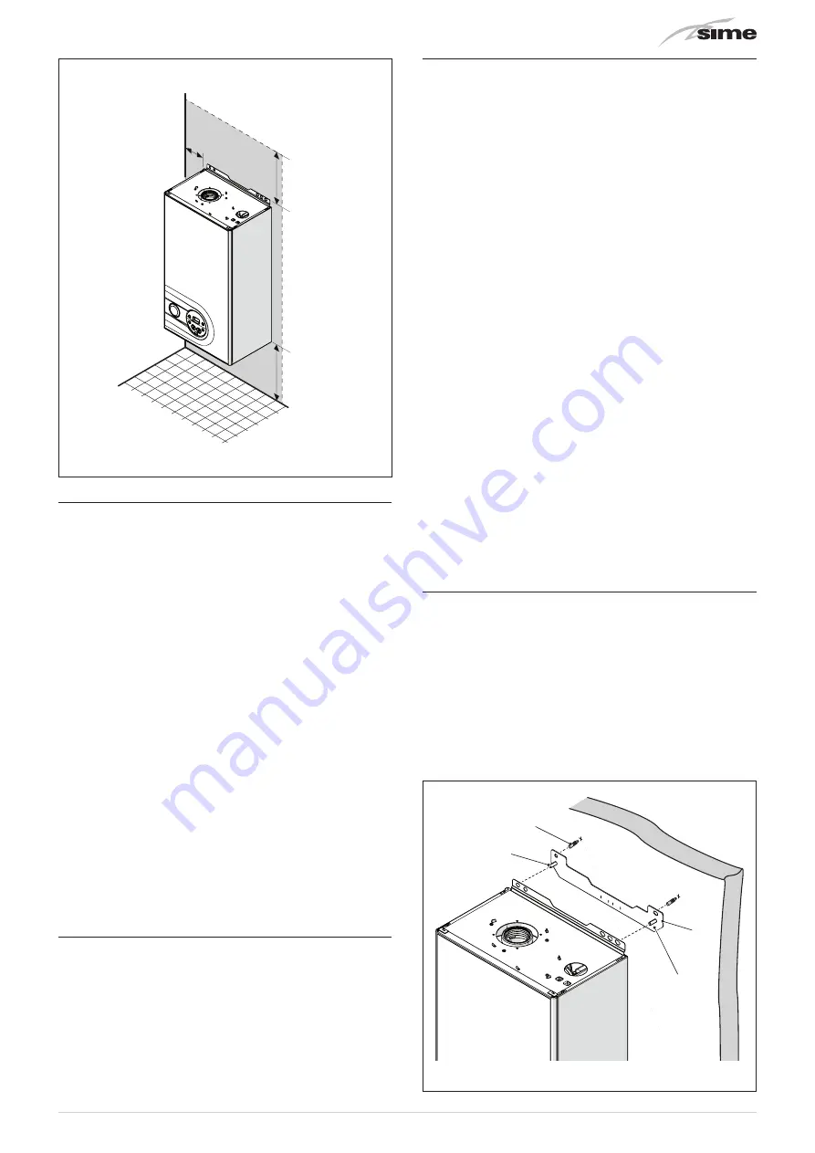
APPROXIMATE MINIMUM DISTANCES

≥ 15 mm

≥ 200 mm

≥ 200 mm

Fig. 17

6.5 

New installation or installation of a re-

placement appliance

The boiler must be installed in a fixed location and only by spe-

cialized and qualified person in compliance with all instructions 

contained in this manual.

The installation of this boiler must be in accordance with the 

relevant requirements of the current Gas Safety (installation 

and use), the local building regulations and I.E.E. wiring reg-

ulations.

Detailed recommendations for air supply and fluing are given 

in BS5440.

The following notes are for general guidance: it is not neces-

sary to have a purpose provided air vent in the room or com-

partment in which the appliance is installed.

CAUTION

It is a condition of the warranty that the boiler is in-

stalled in accordance with the instructions in this 

manual. The boiler must be registered with Gas Safe 

Register, the Benchmark record must be completed 

and the boiler is serviced annually and recorded in 

this manual.

CAUTION

If the domestic water supply is metered or should a 

water meter be added at a later time, a small expan-

sion vessel should be included in the domestic water 

pipework.

6.6 

Cleaning the system

Before connecting the boiler it is recommended that the system 

be flushed in accordance to BS 7593, to eliminate any foreign 

bodies that may be detrimental to the operating efficiency of 

the appliance.

CAUTION

Failure to flush and add inhibiter to the system may 

invalidate the warranty.

6.7 

Characteristics of feedwater and system 

treatment

–  All recirculatory systems will be subject to corrosion unless 

an appropriate water treatment is applied. This means that 

the efficiency of the system will deteriorate as corrosion 

sludge accumulates within the system, risking damage to 

pump and valves, boiler noise and circulation problems.

–  Before connecting the boiler the associated central heating 

system must be flushed in accordance with the guidelines 

given in BS 7593 “Treatment of water in domestic hot water 

central heating systems”.

– 

Sime Ltd

 recommends only the use of FERNOX products for 

the flushing and final treatment of the system water. This is 

particularly important in hard water areas. Failure to flush 

and add inhibitor to the system may invalidate the appliance 

warranty. Artificially softened water must not be used to fill 

the heating system. Naturally soft water areas can corrode 

aluminium heat exchangers. Adding Fernox F1 or Mb-1 will 

guard against corrosion.

– 

Sime Ltd

 promote the fitting of TF1 System filter with any new 

boiler installation.

–  It is important to check the inhibitor concentration after in-

stallation, system modification and annually on a service visit 

in accordance with the manufacturer’s instructions. (Note 

on benchmark service record this has been complete). Test 

kits are available from inhibitor stockists; the return of the 

Fernox test report should be kept with the Benchmark to val-

idate warranty.

–  Where Central heating systems are susceptible to freezing 

a mixture of inhibitor and anti-freeze should be added in ac-

cordance with the DWTA code of practice and the Manufac-

tures instructions.

–  The addition of sealing agents to system water is not rec-

ommended because deposits can be left in heat exchanger 

causing circulation issues.

6.8 

Boiler installation

Murelle Pro HE MkII

 are supplied with a hanging bracket and a 

template to assist installation.

For installation:

–  position the bracket (1) on the wall (2), where you want to 

install the boiler

–  check that it is straight and mark where to make the holes 

for the plugs

–  drill the holes and insert the expansion plugs (3) which will 

be used to fix the bracket securely

–  hook the boiler onto the pins (4) and secure it using the nuts 

and washers supplied.

1

2

3

4

Fig. 18

Summary of Contents for MURELLE PRO HE MkII

Page 1: ...BENCHMARK SECTION PLEASE READ THE IMPORTANT NOTICE WITHIN THIS GUIDE REGARDING YOUR BOILER WARRANTY Cod 6316191 08 2013 BRAVA DGT HE 25 30 35 199838 INSTALLATION AND SERVICING INSTRUCTIONS ENSURE THAT...

Page 2: ...into its installation location Manoeuvring the boiler may include the use of a sack truck and involve lifting pushing and pulling Caution should be exercised during these operations Operatives should...

Page 3: ...3...

Page 4: ...ssioning instructions for filling in the checklist at the back of this installation guide Note All Gas Safe registered installers carry a ID Card You can check your installer is Gas Safe Registered by...

Page 5: ...wing opera tions must be carried out set the main isolation switch to OFF close the gas and water valves for the water heating system To ensure continued efficient opera tion of the appliance it is re...

Page 6: ...the main switch to OFF and closing the gas supply Do not modify the safety or adjustment devices without authorization and in structions from the manufacturer d DO NOT Do not block the condensate dra...

Page 7: ...late for the serial number and year of manufacture SYMBOLS a WARNING To indicate actions which if not carried out correctly can result in injury of a general nature or may dam age or cause the applian...

Page 8: ...8...

Page 9: ...CALLING ON 0800 408 5500 OR ALTERNATIVELY WWW GASSAFEREGISTER CO UK 1 OPERATING THE MURELLE PRO HE MkII 10 1 1 Control panel 10 1 2 Preliminary checks 11 1 3 Ignition 11 1 4 Adjusting the delivery te...

Page 10: ...bol appears when the boiler is operating in Summer mode or if only the domestic hot water mode is enabled via the remote control If the symbols land nare flashing this indicates that the chimney sweep...

Page 11: ...tion After having carried out the preliminary checks proceed as fol lows set the main system switch to ON on the display check that the operating mode on the display is SUMMER l and if necessary selec...

Page 12: ...fied technical professional 1 6 1 Maintenance request When it is time to perform maintenance on the boiler SE shows on the display Contact the technical assistance service to organise the nec essary w...

Page 13: ...lly qualified personnel who will follow the indications provided in the INSTALLATION AND MAINTENANCE MANUAL 3 2 External cleaning a WARNING Should it be necessary to access the areas in the bottom par...

Page 14: ...14...

Page 15: ...5 1 Characteristics 16 5 2 Check and safety devices 16 5 3 Identification 16 5 3 1 Technical Data Plate 17 5 4 Structure 18 5 5 Technical features 19 5 6 Main water circuit 20 5 7 Sensors 20 5 8 Expan...

Page 16: ...agnostic param eters with error code display when the fault occurs This makes repair interventions easier and allows appliance op eration to be restored correctly combustion control function this func...

Page 17: ...AME MAX USEFUL OUTPUT 50 30 C MAX OPERATING PRESSURE MAX USEFUL OUTPUT 80 60 C MAX HEAT INPUT WATER CONTENT IN BOILER FLOW RATE MAX OPERATING PRESSURE ELECTRICAL SUPPLY MAXIMUM ABSORBED POWER MAX HEAT...

Page 18: ...y thermostat TS 8 Delivery sensor SM 9 Fan 10 Condensate siphon 11 Diverter valve 12 Domestic hot water sensor SS 13 Control panel 14 Domestic hot water heat exchanger 15 Gas valve 16 Domestic hot wat...

Page 19: ...rate l min 2 2 Max PMW Min pressure bar 6 0 5 7 0 5 kPa 600 50 700 50 ENERGY PERFORMANCE HEATING Heating seasonal energy efficiency class A A Heating seasonal energy efficiency 93 93 Sound power dB A...

Page 20: ...ock 5 7 Sensors The sensors installed have the following characteristics Dual sensor thermal safety output NTC R25 C 10k domestic hot water sensor NTC R25 C 10k external sensor NTC R25 C 10k Correspon...

Page 21: ...ers or decrease the values This allows the engineer to scroll through the parame ters or increase the values o This allows the engineer to confirm the selected param eter or to modify the value or to...

Page 22: ...ol instead of room thermostat OP Mechanical timer Note Volt free external controls TA are connected to terminals 5 and 6 after removal of the link Fig 13 m CAUTION Installer must Connect the boiler to...

Page 23: ...23...

Page 24: ...tions by competent persons and that it meets the require ments of the appropriate Building Regulations The Benchmark Checklist can be used to demonstrate compliance with Building Regulations and shoul...

Page 25: ...let collection 28 6 11 Gas supply 28 6 12 Connecting the flue 29 6 12 1 Flue Terminal Positions 29 6 12 2 Installation of coaxial flues 60 100mm 80 125mm 30 6 12 3 Installation of separate ducts 80mm...

Page 26: ...35 W mm 400 D mm 250 250 H mm 700 Weight kg 28 5 30 0 6 3 Handling Once the packaging has been removed the appliance is to be handled manually tilting it slightly lifting it and applying pres sure in...

Page 27: ...to pump and valves boiler noise and circulation problems Before connecting the boiler the associated central heating system must be flushed in accordance with the guidelines given in BS 7593 Treatmen...

Page 28: ...t have a continuous fall from the boiler and must be resistant to corrosion by condensate copper or steel is NOT suitable It should be noted that the connection of a condensate pipe to a drain may be...

Page 29: ...uisance should be avoided 75 mm 200 mm 75 mm 300 mm 1 200 mm 600 mm 300 mm 600 mm 1 200 mm 300 mm 3 in 8 in 3 in 12 in 48 in 24 in 300 mm 12 in 12 in 24 in 48 in 300 mm 12 in 1 500 mm 300 mm 300 mm 60...

Page 30: ...e 8095970 reduces the available length by 1 0 metres HORIZONTAL FLUES MUST BE LEVEL NOTE Before connecting accessories it is always advisable to lubricate the internal part of the gaskets with silicon...

Page 31: ...90 bend code 8077450 0 25 3 a Extension 80mm L 1000 code 8077351 3 b Extension 80mm L 500 code 8077350 7 45 bend code 8077451 0 20 9 Inlet exhaust fitting code 8091401 10 Articulated tile code 8091300...

Page 32: ...is boiler The installation of this boiler must be in accordance with the relevant requirements of the current Gas Safety installation and use Regulation 1998 the local building regula tions and I E E...

Page 33: ...d on the packaging of the product itself Climatic curve Delivery temperature 20 15 10 5 0 10 15 5 20 80 90 70 60 50 40 30 20 C C K 9 K 7 K 8 K 5 K 6 K 3 K 4 K 2 K 1 External temperature Fig 29 m CAUTI...

Page 34: ...rds and release it from the top by lifting it 1 2 Fig 34 Domestic hot water circuit open the domestic hot water inlet isolation valve 4 open each of the DHW taps until air is expelled Heating circuit...

Page 35: ...t the top push ing it forwards and securing it with the screw 1 which was removed previously 6 14 3 EMPTYING operations Domestic hot water circuit close the domestic hot water circuit isolation valve...

Page 36: ...r press and hold down the buttons o and at the same time for approximately 12 seconds until the flashing symbols l and n appear on the display as soon as the symbols begin to flash release the buttons...

Page 37: ...CONFIGURATION tS 0 1 Index showing boiler power in kW 2 30 kW 3 35 kW 1 2 o 3 tS 0 2 Hydraulic configuration 0 combi 1 N A 2 N A 3 N A 4 N A 5 N A 6 N A 1 0 tS 0 3 Gas Type Configuration 0 G20 1 G31...

Page 38: ...isconnect the appliance from the mains power by setting the main switch to OFF as a precautionary measure close the gas isolation valve NOTE after having repaired the fault when the alarm number appea...

Page 39: ...ervice 1 199 months 1 CO 0 7 total no of calibrations 1 199 x 1 1 TABLE OF ACTIVATED ALARMS FAULTS Type No Description AL 00 Last activated alarm fault AL 01 Last but one activated alarm fault AL 02 T...

Page 40: ...ck is connected directly to the gas valve 7 7 Gas conversion Murelle Pro HE MkII models can work with G20 or G31 without the need for any mechanical conversion Simply select parame ter 0 3 see Paramet...

Page 41: ...at the system components and pipes are not hot risk of burning a WARNING Before carrying out any interventions described isolate the power supply isolate the gas cock avoid contact with any hot surfac...

Page 42: ...w and return valves and drain the boiler Check the expansion vessel pressure is not less than 1 bar If this is not the case pressurize it to the correct value see sectionExpan sion vessel page 20 8 4...

Page 43: ...t your network provider AL 40 Incorrect supply fre quency detected Contact your network provider Type No Fault Solution AL 41 Flame loss more than 6 consecutive times Check the ignition detec tion ele...

Page 44: ...pressure Check expansion vessel Limited production of domestic hot water Check the diverter valve Check that plate heat exchanger is clean Check domestic hot water circuit valve 8 6 1 Maintenance requ...

Page 45: ...rate m hr OR ft hr r a b m e t a r m u m i x a m t a e r u s s e r p g n i t a r e p o r e n r u B OR r a b m e t a r m u m i x a m t a e r u s s e r p t e l n i s a G Cold water inlet temperature C...

Page 46: ...Record At max rate CO ppm AND CO At min rate Where Possible CO ppm AND CO Comments Signature SERVICE 04 Date Engineer name Company name Telephone No Gas safe register No Record At max rate CO ppm AND...

Page 47: ...47 9 EXPLODED VIEWS...

Page 48: ...48...

Page 49: ...49...

Page 50: ...50...

Page 51: ...ring X X 54 6227462 Flowing pipe to C H system X X Pos Code Description Murelle Pro HE 30 35 55 6226412 O ring 3068 X X 56 6231372 Temperature sensor X X 57 6146729 100 C safety stat X X 58 6226601 Sp...

Page 52: ...ork must be a minimum of 19mm ID typically 22mm OD plastic pipe or as per manufacturer s instructions and this should fall a minimum of 45mm per metre away from the boiler taking the shortest practica...

Page 53: ...ir break is required Key 1 Boiler 2 Visible air break 3 75 mm trap 4 Visible air break and trap not required if there is a trap with a minimum condensate seal of 75 mm incorporated into the boiler 5 S...

Page 54: ...nimum condensate seal of 75 mm incorporated into the boiler In this case the 100 mm is measured to the trap in the boiler 5 Sink basin bath or shower 6 Open end of condensate discharge pipe direct int...

Page 55: ...er level end cut at 45 Note the maximum external condensate discharge length is 3 metres 6 Minimum internal diameter 19 mm 7 Pipe size transition 8 Minimum internal diameter 30 mm 9 Water weather proo...

Page 56: ...used External waste pipes from kitchens utility rooms or bathrooms such as sink basin and bath or shower waste outlets should be insulated with waterproof UV resistant class 0 material terminated bel...

Page 57: ...4 5 75mm sink waste trap 2 5 4 3 Key 1 Boiler 2 Visible air break at plug hole 3 75 mm sink basin bath or shower waste trap 4 Sink basin bath or shower with 5 Open end of condensate discharge pipe di...

Page 58: ...ons should be followed The condensate pipe should be run internally as far as possible before going externally and the pipe diameter should be increased to a minimum of 30mm ID typically 32mm OD befor...

Page 59: ...of 75mm incorporated into the boiler 5 Soil and vent stack 6 Invert 7 450mm minimum upto three storeys 8 Minimum internal diameter 19 mm 9 Pipe size transition point 10 Minimum internal diameter 30mm...

Page 60: ...ub zero temperatures i e 15 C for 48 hours BS6798 refers to devices that gas BS6798 section 6 3 8 note 4 The boiler manufacturer s instructions will disposal of the condensate Additional Measures meas...

Page 61: ...wed Insulation Materials Insulation used for external condensate pipes sink or washing machine waste pipes should be of class O grade with an outer coating that is weather proof is recommended for 32m...

Page 62: ...ate discharge pipe from boiler 2 Pipe size transition point 3 Water weather proof insulation 4 43mm 90 male female bend 5 External rain water pipe into foul water 6 External air break 7 Air gap 8 9 Mi...

Page 63: ...14 or boiler installation manual for soakaway design requirements any above ground section of condensate discharge pipe should be run and insulated as described above Figure 7 following page shows a s...

Page 64: ...incorporated into the boiler refer to manufacturers instructions 5 External length of pipe 3 m maximum 6 Open end of condensate discharge pipe direct into gully 25 mm min below grating but above water...

Page 65: ...be run either above or below round level End cut at 45 3 Diameter 100 mm minimum plastic tube 4 Bottom of tube sealed 5 Limestone chippings 6 Two rows of three 12 mm holes at 25 mm centres 50 mm from...

Page 66: ...onnected to the boiler Is O2 less than or equal to 20 6 and CO2 less than 0 2 VERIFY FLUE INTEGRITY Analyser readings indicate that combustion products and inlet air must be mixing Further investigati...

Page 67: ...n GJ C H seasonal energy efficiency D HW energy efficiency Sound power dB A Specific precautionary measures to be adopted at the time of assembly installation or maintenance of the equipment are conta...

Page 68: ...perature regime b P1 7 1 kW At 30 of nominal heat output and low temperature regime 1 97 7 Auxiliary electricity consumption Other items At full load elmax 0 044 kW Standby heat loss Pstby 0 088 kW At...

Page 69: ...e regime b P1 8 9 kW At 30 of nominal heat output and low temperature regime 1 97 7 Auxiliary electricity consumption Other items At full load elmax 0 047 kW Standby heat loss Pstby 0 088 kW At part l...

Page 70: ...70...

Page 71: ...71...

Page 72: ...Sime Ltd 1a Blue Ridge Park Thunderhead Ridge Glasshoughton Castleford WF10 4UA Phone 0345 901 1114 Fax 0345 901 1115 www sime co uk Email enquiries sime co uk...

Reviews: