4.3.1
Filling the system
Before going ahead with the boiler
connection, it is best to let some
water flow in the pipes to eliminate
any f or eign bodies t hat would
pr event t he equipment fr om
operating correctly.
The system must be filled slowly to
allow air bubbles to comes out from
the designated outlets of the heating
system.
In closed-circuit heating systems, the
cold loading pressure of the system
and the pre-blowing pressure of the
expansion vessel must match or in any
case not be less than the height of the
system's static column (for instance,
f or a 5-me tr e s t atic column t he
preload pressure of the vessel and the
loading pressure of the system must
be at least 0.5 bar).
4.3.2
Properties of the
water supplied
The water supplied in the heating
circuit must be treated in accordance
with the UNI-CTI 8065 standard.
Please note that even small deposits
just a few millimetres thick generate,
due to their low thermal conductivity, a
consider able over heating of t he
boiler's side surfaces, resulting in
serious inconvenience.
IT IS ABSOLUTELY ESSENTIAL TO
TREAT THE WATER USED FOR THE
HEATING SYSTEM IN THE FOLLOWING
CASES:
– Ver y lar ge sy s t ems (wit h lar ge
amounts of water).
– Fr equent suppl y of wat er t o
replenish the system.
– If it is necessar y t o emp ty t he
system, completely or just in part.
4.4
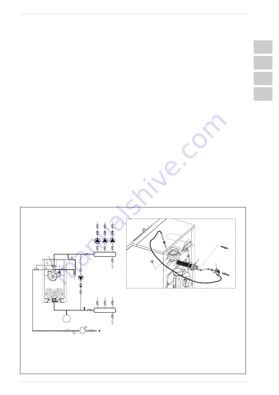
SAFETY HEAT EXCHANGER
(fig. 5)
The t her mal heat exchanger is
supplied in a kit:
- code 5201900 for PIROEMME 4
- code 5201901 for PIROEMME 5
- code 5201902 for PIROEMME 6
- code 5201903 for PIROEMME 7.
The kit mus t be used on closed
expansion vessel systems. Its function
is to cool the boiler when temperature
exceeds by using a thermal drain
valve, which is hydraulically connected
to the heat exchanger inlet. Once the
thermal drain valve (VS) has been
connected insert the socket with the
probe inside the seat obtained on the
rear head. In correspondence with the
heat exchanger outlet, place a drain
pipe with a funnel and siphon that take
to a suitable drain. The drain must be
controlled at sight.
CAUTION: Should this precaution not
be t aken, an activation of t he
t her mal dr ain val v e can cause
damage to persons, animals and
objects for which the manufacturer
cannot be held responsible.
Before commissioning the boiler,
ensure that the water flow to the
thermal drain valve is guaranteed.
4.5
ASSEMBLY INSTRUCTIONS
The casing pack cont ains t he
insulation material of the boiler body,
the eight suppor t brackets of the
casing, the door microswitch bracket,
the bypass device and the clamping
screws.
The second pack just contains the
contr ol panel and t he t hir d one
9
ENG
ES
IAF
M
MANDATA
IMPIANTI
RITORNO
IMPIANTI
R
1
9
4
5
6
1
11
3
1
1
1
1
1
1
1
1
1
2
3
7
8
10
10
10
1
Valvole di sezionamento
2
Circolatori
3
Valvole non ritorno
4
Collettore mandata
5
Collettore ritorno
6
Vaso espansione
7
Riduttore di pressione
8
Filtro / addolcitore
Eventuale pompa anticondensa
10
Scarichi
11
Sonda eventuale pompa anticondensa
M
Mandata
impianto
R
Ritorno
impianto
IAF
Ingresso
acqua
fredda
ST
12
12
Valvola di scarico termico
ST
Scambiatore termico
di sicurezza
Valvola sic. impianto 3 bar -1/2”
9
VS
VS
Fig. 5
ST
VS
SC
ARICO
ALIMENT
AZIONE
ALIMENT
A
T
ION
DRAIN
C.H.
FLOWS
C.H.
RETURNS
1
Isolation valves
2
Pumps
3
Non-return valves
4
Flow collector
5
Return collector
6
Expansion vessel
7
Pressure reducer
8
Filter/ softener
9
Anti-condensation pump
10
Drains
11
Anti-condensation pump probe
12
System safety valve 3 bar -1/2”
M
C.H. flow
R
C.H. return
IAF Cold water inlet
ST
Safety heat exchanger
VS
System safety valve


