MA47
Datum 16.06.2000
Art.Nr. 76671
Z.Nr. 8664049
Änd.Stand 201/00
1 1
Press key
to confirm and store the new
value.
If key
has not been pressed and no value has
been entered during approx. 30 seconds, the
display returns to display mode without making
any value correction.
Precondition: Menu point (rEF_F) in pro-
gramming mode must be programmed to "EIn" .
Offset value correction
Press key
(for at least 3 seconds) to activate
offset value input.
The display shows alternatingly the current refe-
rence value and the symbol „oFF“.
Use the arrow keys to enter a new value.
Press key
to confirm and store the new value.
If key
has not been pressed and no value has
been entered during approx. 30 seconds, MA47
returns automatically to display mode.
Precondition: Menu point (oFF_F) in pro-
gramming mode must be programmed to "EIn" .
Reset
Press key
to set the display to the program-
med reference / offset value.
Any programmed ‘incremental dimension’ (which
is signaled by the blinking comma) will be taken
into account.
8. Manual calibration
For setting the display to the reference / offset
value either
• press key
or
• briefly activate (by connecting to GND) input
RFS (terminal no. 6).
Precondition: Menu point_rFS_ in programming
mode must have been programmed to "Hand" .
The display can thus be zeroed, if the reference
value was previously programmed to 0.
9. Automatic calibration
Electronic linking of the signals from a reference
point transmitter (eg. cam switch or limit switch)
with the index pulse (index marker) of the con-
nected encoder will calibrate the measuring
display, ie. a start position is defined. During
mounting of the reference point transmitter,
please adjust the incremental encoder in such a
way that the index pulse only appears when the
reference point switch is activated.
The contact of the reference switch must only
e active for less than one revolution of the
encoder (see fig. 7).
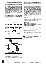
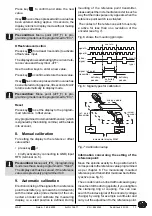
Fig. 6 shows the mounting principle.
Fig. 6: Signal types for calibration
Fig. 7: Calibration setup
Information concerning the setting of the
reference point:
Move the spindle exactly to the position which
corresponds to the reference value programmed
as per chapter 8. The mecanically mounted
reference point transmitter must now be definite-
ly active (see fig. 5).
The encoder can be turned without causing any
movement of the driving spindle, if you untighten
the clamping ring or coupling. You can now
search the index signal of the encoder (voltage
change) by using for example a voltmeter and
carry out the adjustment to the reference point.
one turn
signal A
signal B
index-
signal
type O
type I
signal ref. point
transmitter
definitely
passive
definitely
active
definitely
passive
drive
driving spindle
ref. point
transmitter
increm.
encoder
incremental display MA07


