background image

MA47

Datum  16.06.2000

Art.Nr. 76671

Z.Nr. 8664049

Änd.Stand 201/00

7

ENGLISH

1. Safety information

• In order to carry out installation correctly, we
strongly recommend this document is read very
carefully. This will ensure your own safety and
the operating reliability of the device.

• Your device has been quality controlled, te-
sted and is ready for use. Please respect all
warnings and information which are marked
either directly on the device or in this document.

• Warranty can only be claimed for components
supplied by SIKO GmbH. If display MA47 is
used together with other products, the warranty
for the complete system is invalid.

• Repairs should be carried out only at our
works. If any information is missing or unclear,
please contact the SIKO sales staff.

2. Identification

Please check particular type of unit and type
number from the identification plate. Type num-
ber and the corresponding execution are indica-
ted in the delivery documentation.

e.g.    MA47-0023

type number
type of unit

3. Installation

The unit should be used only according to the
protection level provided. Protect MA47, if ne-
cessary, against environmental influences such

User Information

MA47

Electronic Display

as sprayed water, dust, knocks, extreme tempe-
ratures.

Built-in housing EG

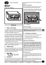
Push the display into the panel cut-out (1) until
the panel clips (2) hold the housing loosely.

Press the lateral centering (3) slightly down and
push the housing into the cut-out (1) until the
panel clips (2) snap completely.

Fig. 1: Installation

Bench housingTG

Remove rubber plugs before fixing the housing.

Attention ! The max. thread depth of 6.5 mm
must be absolutely respected!

4. Electrical connection

• Wiring must only be carried out with power off!

• Provide stranded wires with ferrules.

• Check all lines and connections before swit-
ching on the equipment.

Interference and distortion

All connections are protected against the effects
of interference. The location should be selec-
ted to ensure that no capacitive or inductive
interferences can affect the translation mo-
dule or the connection lines!
 Suitable wiring
layout and choice of cable can minimise the
effects of interference (eg. interference caused
by switching power supplies, motors, cyclic
controls and contactors).

Necessary steps:

• Only screened cable should be used. Screen
should be connected to earth at both ends. Wire
cross section is to be at least 0,14 mm², max.
0,5 mm².

• Wiring to the screen and the ground (0V) must
be secured to a good point and a large surface
area to allow minium impedance.

1

3

2

Summary of Contents for MA47

Page 1: ...o zu wählen dass induktive oder kapazitive Stö rungen nicht auf die Anzeige oder deren Anschlussleitungeneinwirkenkönnen Durch geeignete Kabelführung und Verdrahtung kön nen Störeinflüsse z B von Schaltnetzteilen Motoren getakteten Reglern oder Schützen vermindertwerden Benutzerinformation MA47 Elektronische Messanzeige DEUTSCH 1 Sicherheitshinweise Lesen Sie vor der Montage und der Inbetrieb nahm...

Page 2: ...bb 2 Spannungsversorgung DieSpannungsversorgungerfolgtüberdierück seitigen Anschlussmöglichkeiten Die Span nungswerte sind abhängig von der Geräteaus führung und sind den Lieferpapieren oder dem Typenschild zu entnehmen ist z B 24VDC 20 Leistungsaufnahme 2 VA ohne Geber 4 1 Anschluss Einbaugehäuse EG Abb 2 Anschlussbelegung EG Alternativ zum mechanischen Referenzpunkt geber Näherungsschalter mit N...

Page 3: ...twerden Betriebsarten Es gibt zwei Betriebsarten in denen das Gerät mittels der Tastatur beeinflußt werden kann 1 Programmiermodus EinmaligeEinrichtung der Anzeige auf die Anwendung 2 Eingabemodus Funktionen die während dernormalenAnwendungbenötigtwerden 6 Programmiermodus Die Anzeige wird ab Werk mit einer Standard einstellungodergemäßBestellungausgeliefert ZurÄnderungundProgrammierungmussinden P...

Page 4: ...gnal mit invertierterLogik _dP_ Nachkommastelle SetzendesDe zimalpunktes _oFF_ Offsetwert Setzen eines Korrek turwertes Offset _rFS_ Referenzschaltertyp Kontaktart des Referenzpunktgebers der als mechanischerSchalteroderNähe rungsschalterausgeführtseinkann Schl Schließkontakt normalerweisege öffnet nur aktiv mit Indexmarke des Gebers oEFF Öffnerkontakt normalerweise ge schlossen nur aktiv mit Inde...

Page 5: ...ert geändert werden Mit Drücken der Taste wird der Wert über nommenundgespeichert Die Messanzeige schaltet wieder in den Anzei gemode zurück falls ca 30 Sekunden keine Tastatureingabe erfolgt oder die Taste ge drückt wird Voraussetzung ImProgrammiermodusmuss derMenüpunktFreigabeReferenzwert rEF_F mit EIn programmiert sein Offsetkorrektur Betätigen der Taste mindestens 3 Sekun den schaltet die Offs...

Page 6: ...endesKlemmringsbzw derKupplung des Inkrementalgebers läßt sich dieser verdre hen ohne die Antriebsspindel mitzubewegen Jetzt können Sie z B mit einem Spannungs messer das Indexsignal des Gebers suchen Spannungswechsel unddurchVerdrehender GeberwelledenReferenzpunktjustieren Wenn sichIndex undReferenzpunktgeber Signalge mäßAbb 6zueinanderbefinden wirdderKlemm ring bzw die Kupplung des Inkrementalge...

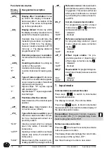
Page 7: ...ser Information MA47 Electronic Display assprayedwater dust knocks extremetempe ratures Built in housing EG Push the display into the panel cut out 1 until the panel clips 2 hold the housing loosely Press the lateral centering 3 slightly down and push the housing into the cut out 1 until the panel clips 2 snap completely Fig 1 Installation BenchhousingTG Removerubberplugsbeforefixingthehousing Att...

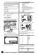
Page 8: ...EG Insteadofmechanicalreferencevaluetransmit ter proximity switch with NPN output ground switching Fig 3 Rear panel type EG No Function Terminal Strip 1 UB encoder supply 2 Signal A 3 Signal B 4 Index signal I O 5 Earth screen encoder supply 6 RFS signal for reference point source 7 Earth for reference point source 8 PE protective conductor 9 N GND 10 L UB 4 2 Conn Bench Top Casing TG Fig 4 Rear p...

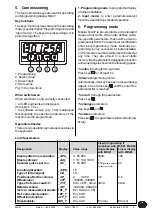
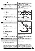
Page 9: ...pro gramming is only necessary at initial installati on Parameterscanbemodifiedandcheckedat any time They are stored in a non volatile memory Eachparameter sdesignation function andvaluerangeisshownonthefollowingpages To enter into programming mode Press key for at least 5 s Toleaveprogrammingmode Automatically ifnokeyhasbeenpressedduring approx 30 s or press key until the end of the parameter lis...

Page 10: ... contact which is normally open only active if encoder has index pulse oEFF Openingcontact whichisnormally closed only active if encoder has index pulse hAnd Manual reset of the counter by ac tivatinginputRFS closingfunction _rEF_ Reference value Absolute datum point referencepoint ofthemeasu ring system This value is either set after system calibration or zeroed by activating the external reset i...

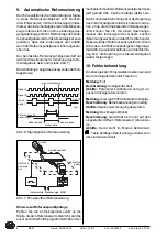
Page 11: ... reference value was previously programmed to 0 9 Automatic calibration Electroniclinkingofthesignalsfromareference point transmitter eg cam switch or limit switch with the index pulse index marker of the con nected encoder will calibrate the measuring display ie a start position is defined During mounting of the reference point transmitter pleaseadjusttheincrementalencoderinsucha way that the ind...

Page 12: ...the clamping ring and the coupling of the incremen tal encoder are retightened 10 Trouble shooting Error states are recognized and shown in the display Message full Description displayoverrun Elimination controlparametersandadjustthem if necessary calibrate display Message blinking display of value 00000 Description operating voltage too low Elimination check voltage supply Message blinking decima...

Reviews: