MA47
Datum 16.06.2000
Art.Nr. 76671
Z.Nr. 8664049
Änd.Stand 201/00
9
5. Commissioning
The four membrane keys are used for operating
and programming display MA47.
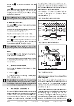
Key functions
The keys’ functions depend upon the operating
mode (see description ‘Programming mode’ and
‘Input mode’). The keys are pressed singly or in
pairs (two together).
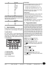
1. Programming
2. Select ‘value’
3. Select 'digit'
4. Store value
Fig. 5: Key functions
When switched on
When switched on and correctly connected:
• all LED segments are displayed
(for approx. 1.5 s)
• the software version ( eg.: 1.00) is displayed
Subsequently the specific parameters of the
machine can be programmed.
Operational modes
There are two operational modes accessible via
the keyboard:
1. Programming mode: to program the display
at initial installation.
2. Input mode: to enter parameters/select
functions used during standard operation.
6. Programming mode
Display MA47 is pre-programmed to standard
values at our works. If the order defines custo-
mer-specific parameters, these will be pre-pro-
grammed at SIKO. For parameter modification
enter into programming mode. Normally pro-
gramming is only necessary at initial installati-
on. Parameters can be modified and checked at
any time. They are stored in a non-volatile
memory. Each parameter’s designation, function
and value range is shown on the following pages.
To enter into programming mode:
Press key
for at least 5 s
To leave programming mode:
Automatically, if no key has been pressed during
approx. 30 s or press key
until the end of the
parameter list is reached.
To scroll through the parameters:
Press key
To change parameters:
Use keys
and
To store parameters:
Press key
; the parameters will scroll automa-
tically.
1
2
3
4
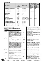
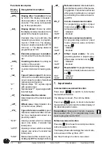
Fixed programming if
combined with MSK01, MSK02
Designation
Display
Value range
Angle display
Linear display
with MRI01
with MB320
Display after one revolution:
_APU_
0...59 999
3600
100
Display divisor:
_Adl_
1; 10; 100; 1000
1
1
Encoder pulses per rev.:
_Str_
0...59 999
512
(number of poles x 8
25
eg. 64 poles x 8 = 512)
Counting direction:
_drEh_
I, E
Type of index signal:
_Ind_
I, O
Positions after the comma:
_dP_
0. ... 0.000
0.0
0.0
Offset value:
_oFF_
-199999...999999
Type of reference switch:
_rFS_
Schl, oEFF, hAnd hAnd
hAnd
Referencevalue:
_rEF_
-199 999...999 999
Increm. measurement enable:
rEL_F
EIn, AUS (on, off)
Ref. value input enable:
rEF_F
EIn, AUS
Offset input enable:
oFF_F
EIn, AUS
Reset enable:
SEt_F
EIn, AUS
EIn (on)
EIn (on)
List of parameters


