AG02
Datum 14.09.2011
Art. Nr. 82270
Änd. Stand 343/11
19
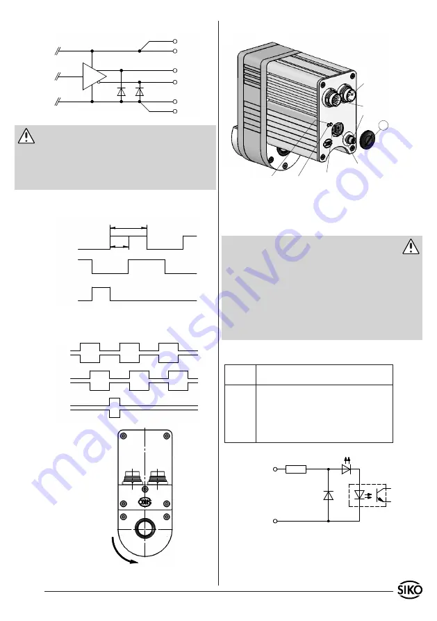
Fig. 8: Wave form
Turning value e;
when mounted
A before B
Network
Encoder
Inputs
P2 (only digital)
P1 (only digital)
LED 1+2
LED 3+4
Fig. 9: Input circuit/digital inputs
right
left
fast/creep
right motion-
left motion-
fast/creep mation-
Fig. 7: Tolerance range of the output channels
6.2 Motor control PWM
Caution: LD24, LD5
The encoder outputs correspond to RS422. Its out
-
puts can drive a load of up to 70 mA, are short-cir
-
cuit-proofed and have a thermic de-energization.
The load per channel must not exceed 35 mA by
using all channels.
Output signals / Wave form
LD5
Line Driver, differential
Potentiometer setup
After removing the covers (1), potentiometers P1
and P2 are accesible.
Warning
• Due to the type of protection, only the covers (1)
may be loosened.
• With the cover (1) loosened, the drive's type of
protection is no longer ensured.
• Set the parameters on the trimming potentiometers
using a 2 mm slot screwdriver.
• When remounting the screws (1) take care that the
seal are seated correctly!
Only with digital inputs:
Potenti-
ometer
Description
P1
Speed setting in fast motion; PWM continuous-
ly adjustable 0 to 100 % (left stop 0 %; right
stop 100 %). Active fast/slow input.
P2
Speed setting in fast motion; PWM continuous-
ly adjustable 0 to 100 % (left stop 0 %; right
stop 100 %). Inactive fast/slow input.


