


19
servo output arm retaining screw. Install the M2 threaded clevis
with its M2 x 22 mm threaded stud in place into the outermost hole
in the servo output arm. Place the arm back onto the servo at the
full "high" throttle position - about 45
O
back from center and also
hold the nylon pushrod at the full "high" throttle position. Using a
marking pen, mark the nylon pushrod where it will be cut and still
accept about 1/4” of the threaded stud. Remove the pushrod and
cut it off at the mark just made.
i) Remove the M2 threaded clevis from the servo output arm
and remove M2 x 22 mm threaded stud from the clevis. Pull the
inner nylon pushrod fully out of the housing tube. The threaded
stud is now threaded into the trimmed end of the inner nylon
pushrod, about 1/4”. Reinstall the pushrod back into its housing
tube and reconnect the metal solder clevis to the throttle arm at the
carburetor. From inside the fuselage, thread the M2 clevis onto the
threaded stud. Reattach the clevis to the servo output arm, again,
at its outermost hole.
The completed throttle linkage system can now be tested and
adjusted to achieve full high and low throttle settings using the
transmitter. This may require repositioning the servo output arm on
the servo and adjusting the metal clevis fore or aft on the threaded
stud.
With the throttle linkage now installed and adjusted, it's time to
make and install the fuel tank.
FUEL TANK ASSEMBLY:
From the kit contents, locate the Fuel Tank Assembly, Bag #16.
The 450 cc (15.2 oz.) fuel tank is now assembled. We suggest
using a simple two-line fuel delivery system in this airplane. One
fuel line is connected to the fuel pick-up or "clunk" line and the
engine's carburetor. This is the fuel line that will be used to fuel
and defuel the tank. The second fuel line is the overflow or vent
line, used when filling the tank.
After filling the tank, this same fuel
line is then connected to the
engine's muffler pressure nipple,
providing some manifold pressure
to the tank.
Note that the
rubber stopper for the tank has two
holes all the way through it. Use
these two holes for the two
aluminum fuel lines.
Also note
that the correct orientation of the
fuel tank body in the tank
compartment is with its neck "up"
in front view.
Gently bend the aluminum overflow tube upward to reach - but not
touch - the top of the tank on the inside, leaving about 3/8” - 1/2”of
exposed aluminum tubing at the front of the tank stopper. The fuel
pick-up aluminum tubing requires no bending. Adjust the length of
the internal silicon tubing to allow free movement of the fuel pick-
up weight inside the tank, at its rear. Like the overflow tubing, leave
3/8” - 1/2” of exposed tube at the front of the stopper. Insert the
stopper assembly into the neck of the tank, firmly seating it to the
tank body. Slide two 8” or so lengths of silicon fuel tubing (not
included) over the two exposed aluminum fuel lines and identify
each of them as "vent" and "carb" with small pieces of tape. Doing
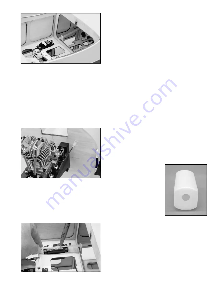
f) The outer throttle tube is now trimmed to the correct
length, ahead of the throttle servo output arm, using a single edge
razor blade.
g) The inner nylon throttle pushrod is now prepared. First
thread the threaded end of the "U" shaped wire pushrod into one
end of the inner nylon throttle pushrod. The threads on the metal
pushrod should be in place to about one half of their overall length.
Insert the opposite end of the inner pushrod tube all the way into
the outer tubing at the firewall. Connect the clevis end of the "U"
shaped pushrod to the outermost hole in the carburetor throttle
arm.
Manually check the action of the pushrod in moving the
throttle arm fully fore and aft. Make any adjustments needed to
create smooth movement.
h) With the throttle pushrod now in place, it is trimmed to its
final length at the servo end. With our Saito 1.00, full "low" throttle
requires the throttle servo to push the pushrod fully forward.
Conversely, full "high" throttle requires the servo to pull the
pushrod fully back.
Plug the throttle servo into the throttle
receptacle in the receiver, turn on the transmitter and then the
airborne radio system. Test the throttle servo movement once
again with your transmitter. If it moves in the wrong direction,
reverse the movement at the transmitter. Now remove the throttle