


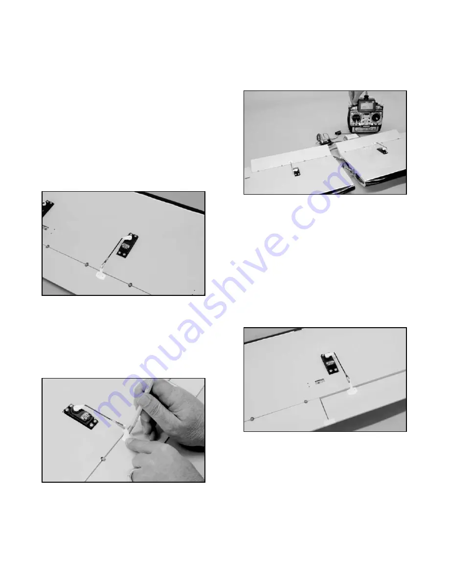
The transmitter can now be used to test the flaps. If necessary,
adjust the clevises to neutralize the flaps at zero, or no-flap. Now
test the flap movement with the transmitter. Use the End Point
Adjustment (EPA) feature in your transmitter to cut the flap servo
throw down to the maximum suggested 30
O
angle (1-7/32" total
movement).
Reinstall and tighten the flap servo output arm
screws.
❑
9) The aileron servo linkages are now installed. Remove the
servo output arm retaining screws. Attach the aileron pushrods
(2-7/8") to each aileron servo output arm, in the outermost hole
location, using the "Z" bend end of the pushrods. Connect a nylon
control horn to each clevis, into the second hole from the end.
Connect a standard Y-harness to each aileron servo lead at the
wing roots.
Connect the Y-harness into the receiver and also
connect the flap connector in place. Turn your transmitter on and
then the receiver. Use a small piece of tape to tape the inboard
end of the aileron to the outboard end of the adjacent flap, aligning
the aileron in neutral. Now place the output arms back onto each
aileron servos, orienting them at 90
O
to the servo body with their
ends facing outboard towards the wingtips.
Orient the control
horn/clevis ends of the pushrods back to the ailerons.
Thread the clevis in or out as needed to position the base of the
control horn flat against the aileron surface with its forward edge at
the rear beveled edge of the aileron. Move the horn left or right as
needed to make the pushrod line-up at a right angle to the servo.
Hold the control horn in place on the aileron and use a sharp
pencil or pointed dowel to mark the control horn mounting hole
locations onto the aileron. Swing the pushrod and horn out of the
way and repeat this process on the opposite aileron servo.
motion moves the output arms towards the flap, reverse the flap
channel through the transmitter. With the servos now moving in the
correct directions and the output arms in place correctly, linkages
between the servos and the flaps can be safely made.
❑
8) The provided flap and aileron pushrods are ready to use.
The wire diameter is .072” and because of this, we found it helpful
to first drill out the two outmost holes in both flap servo output
arms, using a #49 index drill (.072”). This allows the Z-bend end of
the linkages to fit nicely into these holes, without "slop".
On top of each wing panel at the flap joints, use a piece of tape to
hold the flaps in neutral (zero flap) position. Pad your work surface
to protect the wing panels and place them upside down on your
bench. Install a 2-1/2" flap pushrod into each flap servo output
arms at the outermost holes, using the "Z" bend ends. At the
clevis end, install a nylon control horn, using the second hole from
the top. Reinstall the arms back onto each servo in the 45
O
aft
position.
Hold one of the nylon control horns in place at the leading edge of
the flap hinge line. Thread the clevis in our out to allow the control
horn base to rest flat onto the flap surface with its front edge right
at the hinge line. Move the horn left or right as needed to position
it in line with the servo output arm. Hold the horn base in this
position and use a pencil or sharpened dowel to mark the
mounting hole locations for the control horn, onto the flap surface.
Repeat this process on the remaining wing panel and flap.
Using a #57 (.043”) dia. bit, drill two parallel and perpendicular
holes into the flap at the marks just made, about 3/8" deep. Repeat
this on the remaining flap. Because the control horn mounting
holes are undersize for the T2.6 mounting screws, use a #39
(.099") bit to open up these two mounting holes in each control
horn base. The two flap control horns are now mounted to the flap
using the provided T2.6 x 12 mm screws. Remove the tape from
the top sides of both panels to free the flaps.
9