


5
alignment. The best procedure with this type of hinge is to inject
glue into the hole and then insert the hinge. Use a clean cloth
soaked with methanol or rubbing alcohol to wipe off any excess
glue that has oozes out into the control surfaces. Then move to the
next hinge. Epoxy the hinges into the wing first and let dry. Then
slide the aileron in place over the hinges. Again, wipe off any
excess glue.
IMPORTANT NOTE: Be sure to correctly identify which aileron is
for the right wing and which is for the left wing by looking for the
aileron horn plywood mounting pad that is set into the BOTTOM
side of each aileron, underneath the covering.
BOTTOM WING ASSEMBLY:
❑
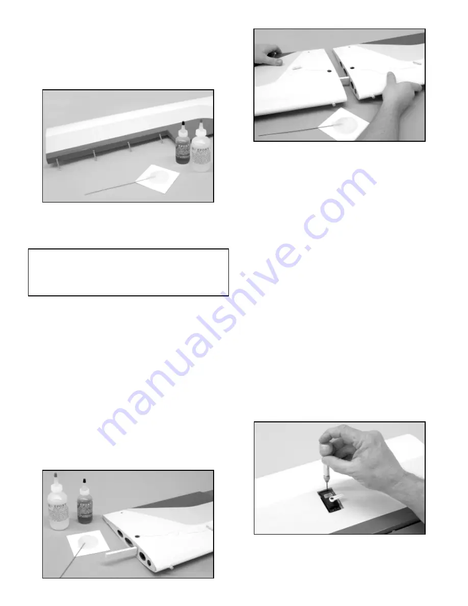
5) Begin assembling the bottom wing halves by mixing an
ample amounts of slow curing epoxy glue. Use a wire, stick, or
small throwaway brush to liberally coat the dihedral brace pockets
in the ends of the wing panels with glue. Then apply a liberal
amount of glue to exposed centers of each wing panel. Next,
apply glue to front and rear face of the dihedral brace and slide
the dihedral brace into one wing panel.
Next, slide the other
wing panel in place over the exposed end of the dihedral brace
joining the two panels at the center. Firmly press the wing panels
together and wipe off any excess glue with a paper towel and
alcohol. Make sure the wing panels are accurately aligned with
each other by checking the alignment of the leading and trailing
edges. Again, use masking tape at the leading & trailing edges of
the joint to hold the panels in the correct position. Place a clean
rag on the floor next to the wall. Stand the wing upright with one
wing tip on the cloth, as vertical as possible, leaning against the
wall. Place a weight on the upper wing tip and allow the assembly
to fully cure.
❑
6) Hinge the ailerons to the wing in the same manner as
described in Step #4 of this assembly manual.
❑
7) Cover the top & bottom wing joint with the provided strips,
as show in Step #3 of this assembly manual.
❑
8) Note that a piece of string has been factory-installed in
each wing panel to make it easier to pull the servo wires and the
attached extension cords through the openings in each wing
panel. Begin by attaching a 24" servo extension to each of the four
the servos. To prevent the connecting plugs from pulling apart
during assembly or from flight vibrations, secure the connecting
plugs together with a piece of tape or heat shrink tubing. Securely
attach the end of the string (servo bay end) to the connecting plug
of the 24" extension. By gently pulling on the opposite end of the
string gently pull while feeding the servo extension into the servo
opening in the wing. Take you time and do not pull too hard on the
string. It is sometimes helpful to stand the wing vertical when
trying to feed the extension through the openings in each of the
wing ribs.
When the extension is through the opening at the
center of the wing, tape it in place to keep it from inadvertently
slipping back through.
Note: Before installing the servos into the wing panels, use your
radio system to center all four servos and to check servo travel
making sure the servo output arms are 90
O
to the servo.
❑
9) Use a pin vise and a small drill bit to drill small pilot holes in
the hardwood mounts for the servo mounting screws. Use the
screws supplied with your radio system to mount the servo
securely in place. Repeat this step for the remaining three aileron
servos.
❑
10) Locate four metal control horns (2 left & 2 right), along with
sixteen 2.6 x 10 mm phillips-head screws for mounting the control
horns. Tape the aileron in the neutral position and lay it upside
down on you bench. Position one of the horns on the bottom
MODELER’S TIP: Apply a thin coat of petroleum jelly, such as
Vaseline
®
, to the hinge knuckle. The petroleum jelly will keep
the epoxy from sticking to the knuckle and causing a bind. Do
not get the petroleum jelly on the round shank of the hinge,
where you want the glue to stick.