SIG Sun Dancer Assembly Manual Download Page 14

14

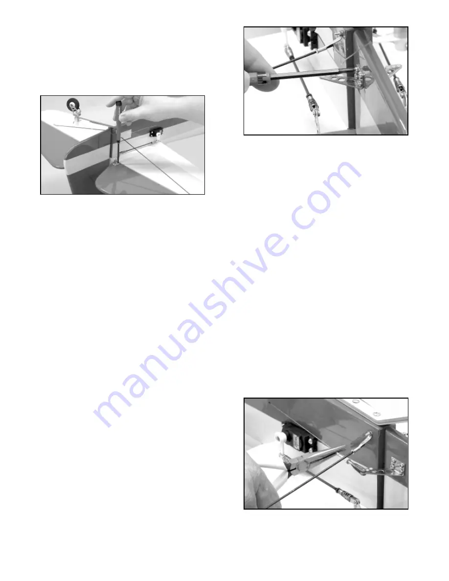
34) You will need two metal control horns for the elevators, one

left and one right, and eight M2.8 x 10mm metal screws. Hold the
control horn in place on the elevator, lined up with the elevator
servo output arm. Make sure the pivot holes in the control horn
line up with the hinge line. Mark the control horn mounting holes
on the elevator with a felt pen. Drill a 3/64" dia. (or #56 drill) pilot
hole for each screw, then screw the horn in place. Repeat this 
procedure on the opposite elevator.

IMPORTANT: After mounting the elevator control horns for the
first time, take them back off and set aside temporarily. Put a few
drops of Thin CA into each of the screw holes in the elevators. The
Thin CA will soak into the threads in the wood, increasing their
holding power. Be sure to use Thin CA, not medium or thick CA.
Let the thin dry completely before remounting the control horns.

35) Because the elevator servos are staggered in the fuselage

two assembled elevator pushrods have been provided for the 
elevators. The 4-40 pushrod for the left elevator measures 5-1/2",
and the pushrod for the right elevator measures 4". Use your radio
to center the elevator servos and then mount the output arms in
place at 90

O

upright. Tape the elevators to the stabilizer in the 

neutral position. Attach the pushrod to the servo output arm in the
second hole from the end of the arm. Adjust the threaded R/C
links to fit into the middle hole of each elevator horn. Remove the
tape holding the elevators in the neural and test the movement of
the elevators with you radio system. Adjust as required to get both
elevators exactly at neutral (if you are using the Miracle "Y" chord,
you can turn the pot adjustment screw to achieve exact neutral
very easily). The final elevator throw adjustments and locking the
R/C links in place with the hex nuts will be made later.

36) Tape the rudder in the neutral position. Remove the tape

holding the pull-pull cable to the fuselage and pull it straight back
against the rudder - note the cable exits the fuselage and runs 
parallel to the bottom of the stabilizer.

Hold the cable in this 

position and mark its location onto the side of the rudder with a
non-permanent marker pen. This line represents the mounting
location for the Metal control horns (one on each side of the 
rudder). Re-tape the pull-pull cable back onto the fuselage side for
now.

37) Place the 90

O

angle of the control horn onto the line just

made. In top view, line up its three linkage holes with the hinge line
of the rudder. Hold the control horn in position and use a marking
pen to mark the four base mounting hole locations onto the rudder.
Four 5/64" dia. holes are now drilled through the rudder at the four
marks just made. Make sure you hold the drill perpendicular to the
rudder when drilling these four holes. Then bolt the two control
horns in place using four M2.5 x 14mm (1/2") and four M2.5 Hex
nuts. Temporarily remove the horns and harden the holes with thin
CA . Allow the glue to cure and re-drill the holes with the 5/64" dia.
drill bit and reinstall the control horns.

BUILDER'S TIP (or straighten up and drill right):
Make a drill guide from a piece of scrap hardwood such as maple
and drill a hole through the scrap with the desired size of drill bit
in a drill press. Mark the location of the hole to be drilled with an
awl and slip the guide (scrap hardwood) over the drill bit. Place
the drill bit in the marked hole and hold the drill guide flush with the
surface. Drill through the surface making sure that your fingers are
out of the way when you drill through the surface.

38) Center the R/C Link in the middle of the threads of the 

rigging coupler and run the knurled stop nut up snuggly against the
R/C Link. Attach the rigging couplers and the R/C Links in the
outer holes of the rudder control horns. Turn on your radio system
and make sure the servo is centered and the trim on the 
transmitter is also set in the middle of its range. Slip one of the
copper swage tubes onto the end of the cable. Then thread the
end of the cable through the small hole in the end of the rigging
coupler and take up any slack in the cable. Loop the end of the
cable back and run it through the copper swaging tube and pull up
the swaging tube up to the rigging coupler about 1/2" away from it.
Do not crimp the swaging tube at this time. Repeat this procedure
for the remaining pull-pull cable.

Next, with the rudder still taped in the neutral position, remove any
excess slack from each of the pull-pull cable by pulling on the short
end of the cable and sliding the swaging to towards the rigging
coupler. Using pliers or a crimping tool, squeeze the copper tube
tightly over the cable locking it in place. Cut off the excess short
end of the cable. Adjust the threaded R/C Links until you get both
pull-pull cables to approximately the same mild tension - Its not
necessary to pull the cables extremely tight.

Remove the tape holding the rudder in place, turn on the radio 
system, and test the movement and centering of the rudder. Make
adjustments if needed. When satisfied with the operation of the
pull-pull system, tighten the knurled stop nut on each rigging 

Summary of Contents for Sun Dancer

Page 1: ...unces of torque These servos or their equivalent from other manufactures can be relied upon to work well throughout the Sun Dancer s flight envelope A standard servo is adequate for the throttle Servo Arms We also suggest that you consider using after market reinforced plastic servo arms such as the Du Bro Super Strength products These output arms are available to fit any brand of servo They are v...

Page 2: ...rts from the plastic bags until needed during assembly All of the required parts screws and bolts will be included in the bag to assemble a particular component of the model Fuselage 1 Fuselage Tail Surfaces 1 Fin 1 Rudder 1 Stabilizer 1 Right Elevator 1 Left Elevator Hinges for above installed but not glued Hatch 1 Fuselage Hatch 4 T2 6 x 8mm PWA Screws Wings 1 Top Right Wing Panel 1 Top Right Ai...

Page 3: ... relatively humid region of the world The wood was therefore holding humidity at the time the parts were covered and bagged Once the parts are removed from their bags and subjected to drier conditions the wood quickly looses moisture and the covering may appear loose This also explains why most iron on covering stay tight in the summer only to loosen a little in drier winter conditions Any wrinkle...

Page 4: ... wing tip and allow the assembly to fully cure 3 After the glue has cured use one of the provided 1 2 x 14 Yellow Covering Strips to cover the bottom wing joint centering the covering over the joint Apply another strip to the top wing again centering the covering over the joint Work slowly and overlap the ends of the two strips by 3 8 at the leading and trailing edges Try to arrange the overlaps s...

Page 5: ...over the top bottom wing joint with the provided strips as show in Step 3 of this assembly manual 8 Note that a piece of string has been factory installed in each wing panel to make it easier to pull the servo wires and the attached extension cords through the openings in each wing panel Begin by attaching a 24 servo extension to each of the four the servos To prevent the connecting plugs from pul...

Page 6: ...m nut against the R C link and push the spring keeper in place over the R C Link Note Just tighten the jam nuts snuggly at this time further adjustments may be necessary during Final set up STABILIZER ELEVATOR ASSEMBLY 12 Hinge the elevators to the stabilizer in the same manner as in Step 4 The hinges are slightly smaller than the hinges used for the ailerons and require the use of a 3 16 drill bi...

Page 7: ...e open and free of any debris In addition remove the muffler carburetor and the spark plug form the engine a Slide the cowl over the engine and the fuselage until it is roughly in place making sure that the drive washer on the engine extends through the opening in the cowl A minimum of 1 16 clearance is required between the spinner backplate and the nose ring on the cowl Tack glue four small piece...

Page 8: ...that must be installed in the nose of the fuselage behind the firewall It must be close enough to the engine to allow the wiring to reach The module wiring consists of the spark plug lead the ground wire the electronic module connection to the prop hub sensor and the battery pack lead The battery pack lead stays in the fuselage and will be connected to a separate battery pack switch used to power ...

Page 9: ...n system and radio flight system as possible to prevent possible interference with the flight radio a We mounted our ignition battery to the inside of the hatch by gluing two pieces of 3 8 x 3 square basswood to the hatch using the dimensions shown in the photo Next drill four 3 32 holes in the basswood and thread in four J bolts Wrap the battery pack in foam and secure it to the hatch with two 64...

Page 10: ... so that the end of the housing is 1 2 past the fuselage former Glue the pushrod housing in place Trim off the excess pushrod housing leaving 1 of the pushrod housing protruding from the firewall After the outer pushrod housing tube is in place remount the engine permanently in place to the firewall Be sure to use thread lock compound on the bolt threads Attach the wiring leads to the engine 21 Th...

Page 11: ...ing it in place Cut off the excess short end of the cable Repeat this process to make the same type of end on the other piece of cable d Attach the rigging couplers to the servo put put arm as shown in the photo Make double sure that the cables do not cross over each other in the rear of the fuselage Each cable should be straight from the servo out put arm to the exit tube in the rear of the fusel...

Page 12: ...tab is square without leaning one way or the other Again measure from the center of the firewall to the tip of the stabilizer When satisfied pin the stab in place and allow the glue to cure BUILDER S TIP Use a sharpened piece of music wire or an awl to perforate the mating surfaces of the stabilizer and the fuselage These small holes or dimples allow epoxy glue to migrate into them and act like sm...

Page 13: ...d wood to wood contact for the best glue joint 32 Using slow curing epoxy apply a liberal amount to the bottom of the fin insides of the rudder fairings the fillet area on top of the fuselage and into the bottom hinge hole in the fuselage Slip the fin rudder in place until it is fully seated in place and secure with straight pins you did install the lower hinge didn t you Wipe off any glue that ha...

Page 14: ... with the hinge line of the rudder Hold the control horn in position and use a marking pen to mark the four base mounting hole locations onto the rudder Four 5 64 dia holes are now drilled through the rudder at the four marks just made Make sure you hold the drill perpendicular to the rudder when drilling these four holes Then bolt the two control horns in place using four M2 5 x 14mm 1 2 and four...

Page 15: ...one of the provided cabane struts into the rear position on the fuselage with two M3 x 15mm socket head bolts and flat washers b Next insert a 6 aileron extension cord into each of the front openings passing the extension between the fuselage sheeting and into the interior of the fuselage Make sure that the extension cord does not interfere with the hardwood mounting blocks for the aluminum cabane...

Page 16: ...Y harness to the bottom end of the 6 chord taped to the left cabane strut That completes the aileron hookups that remain inside the fuselage Later when bolting the bottom wing in place connect the unused end of the right aileron Y harness to the end of the 24 extension chord that you installed in the bottom right wing in step 8 Likewise connect the unused end of the left aileron Y harness to the 2...

Page 17: ...d attach the meter to the bottom wing next to the fuselage as shown in the photo This should also read 0O of incidence If not then look for the lead wires from the servos being caught between the wing and wing saddle or the wing improperly installed Now move the incidence meter to the center of the top wing View the top wing from the front and make sure the wing is close to horizontal level If nee...

Page 18: ...ter mixed with a very small amount of dish soap or SIG Pure Magic Model Airplane Cleaner or Fantastic Windex or 409 type cleaners all work good You will also need a supple squeegee the SIG 4 Epoxy Spreader SIGSH678 is perfect for this job a couple clean soft cloths old tee shirts are great a good straight edge a ruler and a hobby knife with a sharp 11 blade We also suggest that you have some trim ...

Page 19: ...nditions will help in correctly evaluating the flight performance of the model Begin your test flight by making sure the engine is properly set with a reliable idle a strong top end and smooth transition performance Set your engine s high speed needle valve a little on the rich side so that when the airplane noses up the engine will not be over lean and sag Holding up elevator taxi the model to ge...

Page 20: ...e of the huge control movements available from this model However we would urge you to sneak up on such control throws making very sure you have them available to you only on your high rate switches We hope you will enjoy your SUN DANCER for a long time to come Please fly the model safely with constant regard to other fliers spectators and property GOOD LUCK AND SAFE FLYING ...

Page 21: ...del size or full size are not toys Because of the speeds that airplanes must achieve in order to fly they are capable of causing serious bodily harm and property damage if they crash IT IS YOUR RESPONSIBILITY AND YOURS ALONE to assemble this model airplane correctly according to the plans and instructions to ground test the finished model before each flight to make sure it is completely airworthy ...

Page 22: ... providing the most power at a reasonable cost First Place Engines are your best choice for large gasoline powered model airplane power plants All engines use piston and cylinder assemblies from world renowned manufacturers such as Husqvarna and Sachs Makita insuring long life and easy operation Using state of the art CNC machines First Place produces all other major components from high quality b...

Reviews: