


e) Turn the part over and glue the other side of the hinge. Con-
tinue this process until you have glued both sides of all the hinges!
Keep a rag handy to wipe off any excess Thin CA glue. (If you
get some glue smears on the plastic covering, don't worry about
them right now. Once all the hinging is done, you can clean the
smears off the covering with CA Debonder).
f) Let the glue dry 10-15 minutes before flexing the hinges. At
first you might notice a little stiffness in the joint. This will go away
after the hinges have been flexed back and forth a couple dozen
times.
INSTALL AILERON CONTROL HORNS & PUSHRODS
From the kit contents locate:
(2) Nylon Control Horns
(6) M2 x 15 mm Screws
(2) Short Pushrod Wires with M2 Hex Nut
(2) Metal R/C Clevis
(2) Nylon Pushrod Keepers
(2) small pieces of Fuel Tubing
❑
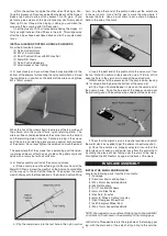
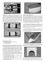
3) Look closely and you will see three holes pre-drilled in the
bottom of the ailerons for mounting the nylon control horns. Screw
the control horn in position on the bottom of the aileron using three
M2 x 15mm screws.
When the tips of the screws begin to emerge at the top surface of
the aileron, add the control horn's nylon retaining plate. The
aileron will be sandwiched between the control horn on the bottom
and the retaining plate on the top. Continue turning in the screws
until the horn and retaining plate are snug against both surfaces
of the aileron. Do not over tighten the screws and crush the wood.
The excess length of the screws that is extending past the retain-
ing plate can be cut off with a pair of side cutting pliers or ground
down with a rotary tool with a cutoff disc.
❑
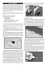
4) Next assemble and install the aileron pushrods.
a) Slide a short piece of Fuel Tubing onto the small end of the
Metal R/C Clevis. Screw the Hex Nut on the Aileron Pushrod Wire
all the way up to the end of the threads. Then screw the metal
clevis halfway onto the threaded end of the Aileron Pushrod Wire.
b) Clip the metal clevis into the last hole in the nylon control
horn. Lay the other end of the pushrod wire over the outer hole
in the servo arm. Use a felt tip pen to mark the wire where it
crosses the hole. Use a pair of pliers to put a sharp 90-degree
bend in the wire at the mark.
c) Insert the bent end of the pushrod into the servo arm, from
the top. Note: You will most likely need to use a 1/16” dia. drill to
open the hole in the servo arm to accept the pushrod wire.
d) Mark and cut off the excess end of the pushrod wire, leaving
1/8” of wire protruding below the bottom of the servo arm.
e) Clip a Nylon Pushrod Keeper in place on the servo end of
the pushrod wire. Snap the free end of the keeper up and over
the protruding end of the pushrod wire, underneath the servo arm.
f) Check that the aileron servo is in neutral position and adjust
the metal clevis as needed to get the aileron in neutral position.
g) Once the ailerons are properly adjusted, insure that the
metal clevis can’t open up and come loose from the control horn
by sliding the piece of Fuel Tubing over the arms of the clevis.
Also tighten the M2 Hex Nut up against the back of the clevis.
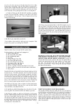
INSTALL THE MAIN LANDING GEAR
Locate the following parts from the kit contents:
(1) Fuselage
(2) Aluminum Main Landing Gear
(3) M4 x 20mm Socket-Head Bolts
(3) M4 Flat Washers
(2) 2-1/2" dia. Main Wheels
(2) 4mm dia. Steel Axles
(4) Hex Nuts; for axles
(4) 4mm ID Wheels Collars; for axles
(1) Right Fiberglass Wheel Pant
(1) Left Fiberglass Wheel Pant
(4) M3 x 10mm Socket-Head Bolts
NOTE: We suggest you use a thread locking liquid (like Locktite
®
)
on all bolts and nuts used in the assembly of the landing gear.
❑
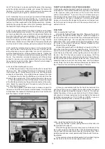
5) Install a Threaded Axle into the large hole of the landing gear
leg, with the plain end of the axle shaft pointing to the outside.
6
FUSELAGE ASSEMBLY