SIG SIGRC76EGARFG Assembly Manual Download Page 10

25) Locate the pre-cut pushrod exit hole for the rudder on the

left side of the fuselage at the back of the plane and repeat step
24) in its entirety to install the rudder pushrod.

Skip this section if your using a glow engine power setup

ELECTRIC MOTOR & ESC INSTALLATION

For this section you will need:

    (1) Fuselage
    (1) Plywood Electric Motor Mount
    (1) Balsa Triangle Stock
    (4) M4 x 20mm Socket-Head Bolts
    (4) M4 Split-Ring Lock Washers
    (4) M4 Flat Metal Washers
    (4) M4 x 16mm Socket-Head Bolts
    (4) M4 Split-Ring Lock Washers
    (4) M4 Blind Nuts
    (2) Plywood Battery Tray
    (1) M3 x 12mm Socket-Head Bolt for battery tray
    (1) M3 Flat Washer for battery tray
    (1) Velcro® Strap
    (1) set Electric Motor, ESC, Prop, Lipo Battery (not furnished)

NOTE: The mounting of the electric motor in the Somethin’ Xtra
assumes that your motor has a typical "X" or "cross" mounting
plate on the back of the motor.  Also note that the firewall portion
of the laser-cut plywood motor mount is adjustable fore and aft to
accommodate different length motors.  Next we will determine
where you should set the firewall for your particular motor.

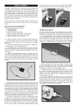
26) Assemble your motor according to the manufacturer's in-

structions.  Then carefully measure the distance from the back of
the mounting plate to the front of the thrust washer*.

The “thrust washer” is the part of the prop adaptor where the

back of the propeller will be located.  

27) For the Somethin’ Xtra, you need a distance from the back

edge of the motor mount to the motor’s thrust washer to end up

exactly 4-1/4”, in order for the cowling will fit properly.

    a) So what you need to do is to subtract the measurement

taken in the previous step (26) from 4.25”.  The result is the dis-
tance you need to set the front of the firewall from the back edge
of the plywood motor mount box.  

(With the motor we are using in

these photos, the motor measurement is 2.77”.  So 

4.25”

minus

2.77” = 1.48”.  Your result may be different depending on your
motor.)

    b) Carefully measure and mark the distance determined in the

previous step from the back side of the motor mount box towards
the front.  Do this along side each of the adjustment slots on both
sides of the box.

    c) After you have the box marked, carefully align the front face

of the firewall to line up with the marks.  Make sure you end up
with the firewall straight and square in the box.  If it is not, recheck
your marks and adjust as necessary.

    d) Tack glue the firewall in place.  Recheck once more to make

sure that the front of the firewall is at the correct distance from the
back of the motor mount box.  That distance plus the length of
your motor must equal 4-1/4”.  When satisfied it is correct, glue
the firewall securely to the rest of the motor mount box.   

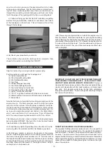
28) Remove the X mount plate from the back of your motor and

center it on the firewall.  Once you are sure it is properly located,
mark the mounting holes with a pencil.  Remove the X mount and
drill out the mounting holes with a 7/32" dia. drill.  Install four M4
Blind Nuts in the holes, on the back side of the firewall.  Put a cou-
ple drops of glue on the flanges of the blind nuts to secure them
to  the  plywood.    Be  careful  not  to  get  any  of  the  glue  in  the
threads. 

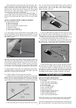
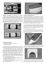
29) Locate the balsa triangle stock provided.  Measure, cut and

glue in pieces of the triangle stock to reinforce as many of the cor-
ner joints of the motor mount box as possible, as shown in the fol-
lowing 2 photos (see arrows).  Then set the mount aside to dry.

10

ELECTRIC POWER SYSTEM

Summary of Contents for SIGRC76EGARFG

Page 1: ...ea 725 sq in 46 7 dm2 Length 48 25 in 1226 mm Flying Weight 5 5 5 lbs 2268 2495 g Wing Loading 16 17 6 oz sq ft 48 53 g dm2 Radio Required 4 Channel with 5 Standard Servos Glow 4 Channel with 4 Standard Servos Electric Glow Power 2 Stroke 40 46 cu in 6 5 7 5 cc 4 Stroke 53 65 cu in 8 6 10 7 cc Electric Power 700 1000 watt Brushless Motor 550 800 kv 75A Speed Control ESC 4S 6S 3000 4000 mAh Lipo Ba...

Page 2: ... engines for the Somethin Xtra 2 STROKE 40 to 46 cu in 4 STROKE 53 to 65 cu in Whatever brand engine you choose take the time to carefully break it in according to the manufacturer s instructions A good running reliable engine is a minimum requirement for the enjoy ment of this or any R C model aircraft PROPELLER FOR GLOW Refer to the engine manufacturer s instructions for recommenda tions on prop...

Page 3: ...cludes the capability of balancing the available voltage in the cells en suring that the battery pack is at peak capacity at the end of the charge cycle This translates to better flight times and a longer life from the battery pack REQUIRED TOOLS For proper assembly we suggest you have the following tools and materials available A selection of glues SIG Thin Medium Thick CA Glue CA Accelerator CA ...

Page 4: ...r you can find the correct tem perature by trial and error Set your iron to a medium setting Glide the iron over some of the covering that is over solid wood such as the sheeted wing center section Observe the covering to see if any bubbles appear If bubbles appear the covering is getting too hot Turn down the temperature and repeat the test If no bubbles appear turn up the heat slightly and repea...

Page 5: ... get it to fall through the openings in the ribs until it emerges at the end rib Once you ve got the plug to the end rib direct it through the round hole in the bottom surface of the wing panel By that time the servo itself should be next to the servo mount cutout and ready for mounting f Fit the servo into the servo mount in the wing panel note that the servo is positioned so that the servo arm i...

Page 6: ...leron Pushrod Wire all the way up to the end of the threads Then screw the metal clevis halfway onto the threaded end of the Aileron Pushrod Wire b Clip the metal clevis into the last hole in the nylon control horn Lay the other end of the pushrod wire over the outer hole in the servo arm Use a felt tip pen to mark the wire where it crosses the hole Use a pair of pliers to put a sharp 90 degree be...

Page 7: ...ng three M4 x 20mm Socket Head Bolts and three M4 Flat Washers bolt the landing gear onto the fuselage TAIL SURFACE INSTALLATION For the following steps you will need 1 Fuselage 1 Wing 1 Stabilizer Elevator set 1 Vertical Fin Rudder Set 2 M6 5 Nylon Wing Bolts 1 Tailwheel assembly including Wheel and Wheel Collars 2 M3 x 15mm Screws 1 Nylon Rudder Steering Clasp with Bolt and Hex Nut 2 Nylon Contr...

Page 8: ... fin and the rear of the fuselage using the same techniques you did for the other hinges refer to page 5 of this manual Make sure to line up the top of the rudder flush with the top of the fin This will ensure the tail wheel bracket lines up correctly Let the hinges dry adequately before proceeding 18 Look closely and you will find three holes pre drilled near the bottom of the rudder for mounting...

Page 9: ... where it crosses over the outer hole in the servo arm d At the tail end unlock the elevator from neutral position and then unclip the clevis from the control horn Remove the clevis and the hex nut completely off of the pushrod and set them aside Now pull the pushrod out of the fuselage from the servo end It will be easier to complete the next three steps with the pushrod out of the airplane e Cut...

Page 10: ... the previous step 26 from 4 25 The result is the dis tance you need to set the front of the firewall from the back edge of the plywood motor mount box With the motor we are using in these photos the motor measurement is 2 77 So 4 25 minus 2 77 1 48 Your result may be different depending on your motor b Carefully measure and mark the distance determined in the previous step from the back side of t...

Page 11: ...of swapping two of the motor wires 31 Next bolt the motor mount box on to the front of the airplane using the M4 x 20mm Socket Head Bolts and Flat Washers pro vided NOTE The best tool for this job is a hex ball driver not fur nished With the hex ball driver you can easily access the top two bolts over the top of the front firewall And you may be able to access the bottom two bolts by going through...

Page 12: ...ing and make any adjust ments needed to get it back in position d Now drill another pilot hole for the upper screw on the other side of the cowling Install the screw e Repeat this process to install the two bottom cowl mounting screws Remove all the tape COOLING IS VERY IMPORTANT 35 With a fully cowled motor it is very important to make sure your motor is getting properly cooled Air must be able t...

Page 13: ...be the most trouble free installation in the Somethin Extra 37 Bolt the two Nylon Engine Mounts on the front of the fire wall using M4 x 25mm Bolts and M4 Flat Washers provided 38 Set your engine in place on the beams of the engine mounts Slide the engine forward or aft on the engine mounts until the front of the engine s thrust washer is 4 1 4 from the front of the firewall Double check to make s...

Page 14: ...he fuselage side Glue the block to both the sleeve and pushrod side THROTTLE PUSHROD FOR 4 STROKE ENGINES 4 stroke glow engines typically have their carburetor on the back of the engine This puts the throttle arm very close to the firewall of the airplane makng the hookup of this end of the throttle pushrod more difficult If you are using a 4 stroke engine you should take a look at some of the spe...

Page 15: ... the fuel tank and the wing joiner tube 50 Mount the receiver on off switch in the fuselage side No tice that there is a cutout for the switch in either side of the fuse lage Remove the covering over the cutout you want to use rhwn bolt the switch in the cutout 51 Mount your propeller on your motor The installation of your glow engine system is complete INSTALL PILOT CANOPY Both glow engine and el...

Page 16: ...time we would urge you to seek the assistance of a qualified R C pilot to help you through the first few test flights Keep the ailerons and eleva tors in their low rates Once airborne get to a reasonable altitude before inputting any trim changes Once the model is trimmed for straight and level flight begin getting the feel for the way it flies We hope that your Somethin Xtra will provide you with...

Reviews: