


INTRODUCTION
Congratulations on your purchase of the Somethin’ Xtra EG ARF.
We hope you will enjoy this R/C sport aerobatic model.
Assembly of your Somethin’ Xtra is fast and simple when follow-
ing the detailed instructions in this manual. We urge you to read
this assembly manual completely before assembly. Familiarize
yourself with the parts and the assembly sequences. The suc-
cessful assembly and flying of this airplane is your responsibility.
If you deviate from these instructions, you may wind-up with prob-
lems later on.
Good luck with the Somethin’ Xtra . Let’s get started!
ADDITIONAL ITEMS YOU WILL NEED TO PURCHASE
In addition to this kit, you will need the following items to complete
your Somethin’ Xtra and make it flyable.
❑
RADIO SYSTEM
The Somethin’ Xtra requires a standard 4-channel radio system
and either four or five standard size servos (four servos is using
electric power, or 5 servos if using glow engine power). "Stan-
dard" size servos typically have 40-60 oz. of torque. In addition,
you'll need two 3"-6” long Servo Extension Cords and one Y-Har-
ness Chord for connection of the two aileron servos to the re-
ceiver. (The length of extension cord you will need depends on
how long the wires are coming off your servos. With Hitec® stan-
dard servos we used 6” long extension cords. Check your servos
and plan accordingly.)
❑
POWER SYSTEM - GLOW OR ELECTRIC?
The biggest decision you will have to make is whether to power
your Somethin’ Xtra with a glow engine (2-stroke or 4-stroke) or
an electric motor. We have flown the Somethin’ Xtra with both
types of power systems, and we make the following recommen-
dations based on our successful on-field experience.
GLOW POWER RECOMMENDATIONS
❑
ENGINE
We recommend the following engines for the Somethin’ Xtra.
2-STROKE - .40 to .46 cu. in.
4-STROKE - .53 to .65 cu. in.
Whatever brand engine you choose, take the time to carefully
break it in according to the manufacturer's instructions. A good
running, reliable engine is a minimum requirement for the enjoy-
ment of this or any R/C model aircraft.
❑
PROPELLER FOR GLOW
Refer to the engine manufacturer’s instructions for recommenda-
tions on proper propeller size for their engine. In our experience,
most .46 size 2-stroke glow engines will fly the Somethin’ Xtra
very nicely with a 10x6 or 11-6 prop.
ELECTRIC POWER RECOMMENDATIONS
❑
700 - 1000 watt BRUSHLESS OUTRUNNER MOTOR
The Somethin’ Xtra is designed to be powered with a 700 to 1000
watt electric brushless outrunner motor. This size motor is some-
times referred to as a "46" class motor to those who like to make
a comparison to a glow motor. Also, the motor you choose should
be rated at 550-800 kv, in order to turn an appropriate propeller.
These motor sizes have worked well in the Somethin’ Extra :
5018-530
5055-670
5052-610
❑
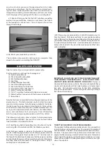
MOTOR MOUNT
A laser-cut plywood adjustable motor mount is included in this kit.
It should work perfectly for any suitable brushless outrunner motor
which has an “X” or “cross” motor mount plate on the back.
❑
75 amp ESC (Electronic Speed Control)
We used the Castle Creations® 75 amp ESC in our Somethin’
Xtra prototypes. This is an excellent "switching type" ESC that
has a built-in BEC (Battery Eliminator Circuit).
2
What do those numbers mean?
NOTE: This numbering system is very common, however there
are exceptions. For instance, some motor manufacturers will
list the actual diameter of the stator (armature) inside the motor
instead of the case diameter. Some may list the length of the
stator inside the motor instead of the case length. Some will
give you both if you dig far enough into their specs. Make sure
you understand the motor manufacturer’s numbering system
when shopping for a motor.