SIG RISER 100 Building And Flying Instructions Download Page 16

COVERING

 
All of the RISER 100 prototypes were covered with Sig Supercoat Iron-On Plastic Covering. The covering is ideal for 
sailplanes because of it's light weight and ease of application. 
 
Start by covering the wing from the main spar to the trailing edge with Transparent Blue. Next, cover the wing panel from 
the spar forward to the leading edge with White. The white should overlap the Blue about 1/2" at the spar! Follow the same 
procedures to cover the top and bottom of all four wing panels. 
 
The fuselage should be completely covered with White Supercoat, and the Red and Blue stripes are then added with the 
striping tape. Completely cover the stabilizer, elevators, fin, and rudder with Transparent Blue. Cut the White for the leading 
edges of the stabilizer and fin from Sig SuperTrim, remove the paper backing, and press the White trim in place. Add Red 
striping tape to the stab and fin to finish them. 
 
NOTE: If you choose another brand of covering material, be sure to read the manufacturer's directions that come with the 
material. Follow their instructions closely when applying the material, as different brand coverings can have slightly different 
handling characteristics and application temperatures. However, the basic techniques for applying iron-on plastic coverings 
of any brand are similar, and the following hints and photos should be helpful.
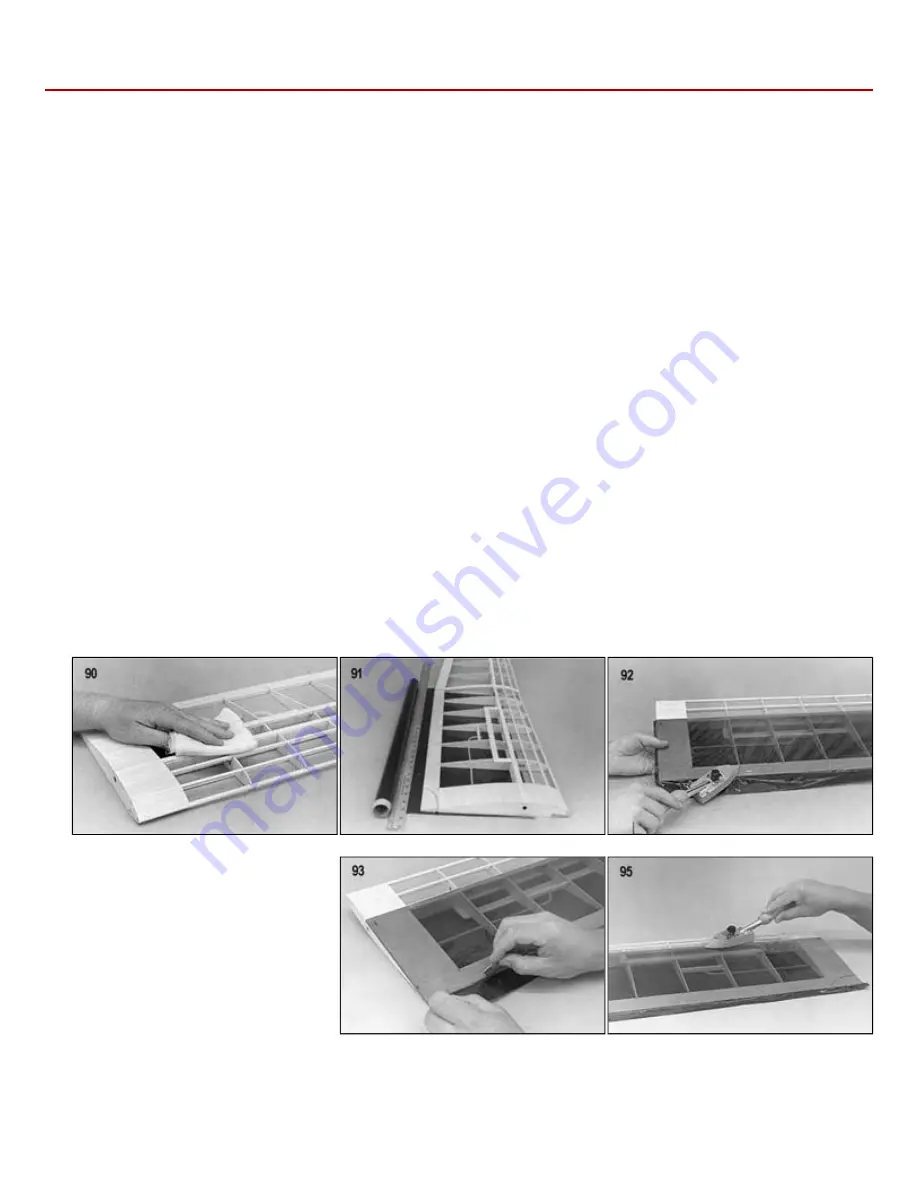
 
90.

 
The structure that is to be covered must be clean, dry, and dust free. Finish sand all the surfaces smooth with 220 or finer 
abrasive paper. Remember that the covering material cannot hide poor workmanship. Whip the entire surface with a tack 
rag or a cloth dampened with alcohol to remove excess dust.

 
91.

 
You should start by covering the bottom of the wing first and then the top of the wing. This leaves the overlapping seam on 
the bottom where it is less visible. Cut the covering to size, allowing approximately one inch excess around the edges. 
Remove the plastic backing from the covering and lay the adhesive side against the structure. Lay it down as smooth as 
possible.

 
92.

 
Using your hot sealing iron (set a 200 deg. F for Sig Supercoat), tack down the covering material at several places around 
the outside edges. Once it is smoothly tacked in place, work completely around the edges, sealing the covering entirely to 
the structure. Don't try to shrink the covering tight at this time. 
 
NOTE: If the surface of the sealing iron becomes contaminated with the colored adhesive that often oozes from under the 
covering, wipe the iron clean with a dry cloth.


93.

 
Trim off the excess covering with a 
sharp razor blade or modeling knife.


94.

 
Go over all of the edges of the covering 
again with the hot sealing iron to make 
sure they are sealed down securely.

 
95.

 
Repeat the process from Step 91 to 
cover the top of the wing. Overlap all 
covering seams at least 3/8" with the 
covering material on the other side.

 
96.

 
To shrink the covering drum tight in the inner areas, we recommend that you use a "heat gun". A household hair dryer will 
not get hot enough to shrink plastic model covering. You need a special heat gun made specifically for shrinking model 
coverings. If you do not have a heat gun, you can also use your sealing iron to shrink the coverings tight. Cover the iron 
with a sock and turn up the heat a little more than it was for sealing the edges to compensate for the sock being on. The 
sock helps keep the iron from scratching the glossy surface of the covering material.

Summary of Contents for RISER 100

Page 1: ...uded for incorporating optional spoilers in the wing of the RISER 100 Spoilers are essential for making consistant spot landings and for other multitask soaring events You will also need to decide whether you want to use the standard rubber band wing mounting system shown on the main side and top view fuse plan or if you want to convert to the optional bolt on wing attachment as shown on plate 2 o...

Page 2: ...ARTS All of the other parts can be identified by the COMPLETE KIT PARTS LIST Sort the different sizes of sticks and sheets into individual piles to avoid confusion during building Cut all long pieces of balsa first followed by medium lengths before cutting up any full length strips into short pieces NOTE Save any scrap balsa and plywood until the model is completely done Some of it may be called f...

Page 3: ...ad Weights 4 10 32 x 1 Nylon Bolts Miscellaneous Parts 1 030 x12 ABS Plastic Skid 1 1 8 x1 2 x14 Servo Mounting Tape 1 Decal 1 Instruction Book 1 38 x50 Plan Plate 1 1 25 x38 Plan Plate 2 You can t get along without a good sanding block An assortment of different size sanding blocks are indispensable tools for model construction A good general purpose block can be made by wrapping a 9 x11 sheet of...

Page 4: ... Some people have experienced allergic reactions when exposed to epoxy or cyanoacrylate glues This is very rare However it is extremely important that such glues and also paints thinners and solvents be used with adequate ventilation to carry fumes away About Printed Wood Parts Some years ago we had kits featuring die cut parts in both thick and thin balsa sizes If the thick parts were cut from dr...

Page 5: ...age Do not remove the rubber bands until all the glue joints have completely dried 8 Cut and glue in place the 1 16 x1 4 balsa fuselage stiffeners where shown on the plan in the area of the hatch 9 Cut and glue in place the 1 16 x1 2 balsa wing saddle stiffener as shown on the plans After the glue has dried trim the balsa to match the wing saddle 10 Drill 3 16 dia holes through the lite ply fusela...

Page 6: ...atch and through the center of the lite ply hold down plate Install a 4 40 blind nut on the bottom side of the hold down plate and bolt the top hatch in place with a 4 40 x 1 bolt 18 That s as far as you can go on the top hatch for now Once the wing is built but before covering the model you must carve out the bottom of the removable top hatch slightly at the rear where it fits down against the wi...

Page 7: ...bing for the rudder and elevator pushrods into the fuselage by passing them through the previously drilled holes NOTE Make sure that the outer pushrods extend out past the former F 3 for 3 4 25 Epoxy the outer pushrod tubing in place at the rear of the fuselage and at the formers F 3 and F 4 26 Use a single edge razor blade to trim the outer pushrod tubing flush with the outside of the fuselage si...

Page 8: ...uctions are provided on the 1 16 die cut plywood sheet 31 Glue and pin in place balsa rib W2 at the polyhedral joint using the polyhedral guage to position the rib at the proper angle 32 Glue and pin in place the top 3 16 x3 8 x26 spruce spar again leaving a small amount of excess on each end of the wing panel Recheck the end ribs W1A and W 2 with the dihedral and polyhedral guages to insure that ...

Page 9: ...0 skip the following steps 38 through 43 and go directly to step 44 to finish the center section 38 Two pieces of 1 4 x1 x12 balsa trailing edge stock is provided for making the spoilers Cut each to length as shown on the plans 39 Notch the two center W 2 ribs of the spoiler bay to allow the spoiler to fit flush with the top of the wing Refer to the drawing Cross Section at Spoiler on plate 2 of t...

Page 10: ...e front of the spruce spar and the turbulators and between the turbulators and the leading edge on both the top and the bottom pf the center section NOTE If you want to use the Optional Bolt On Wing Attachment method described in the next step do not glue the foremost top and bottom pieces of 1 16 sheeting that contact the leading edge in place at this time IMPORTANT NOTE If you have elected not t...

Page 11: ...lace the wing on the completed fuselage and properly align it Make sure each wing tip is the same distance from the rear end of the fuselage Tape the wing in place and carefully drill through the wing and plywood blocks at the same time with a 5 32 drill On the two rear holes remember to keep the drill perpendicular to the top of the wing so the heads of the bolts will seat flush against the wing ...

Page 12: ...xcess on each end of the wing panel Recheck rib W 2 with the polyhedral guage to insure that it hasn t moved 59 Glue and pin in place the 1 4 birch dowel leading edge and the 1 8 x3 16 x24 turbulators Remove the wing panel from the building board and add the bottom turbulator 60 Cut off excess leading edge spruce spars and turbulators with a razor saw so that they are flush with the end ribs W 2 a...

Page 13: ...t go between the front turbulators in place while gluing If so don t worry about bending them into exact position They are thick enough that they can be glued straight sticking out past the ribs and then trimmed down flush with the ribs as shown here 69 Regardless of whether you have elected to use the optional bolt on wing attachment or the standard rubber band wing mounting glue the die cut 1 16...

Page 14: ... braces in place over the plans 80 Block sand both sides of the stabilizer to smooth out any rough areas Be sure to sand the printing off the wood 81 Using a sanding block sand a curve into the ends of the leading edge sticks to blend into the shape of the stab tips Then sand the corners of both the leading edges and the tips round Don t round the corners of the trailing edge of the stab 82 Two 12...

Page 15: ...orsal fin and gussets FG RG 1 and RG 2 in place 87 Cut pieces of 1 8 x1 4 balsa for the cross bracing and glue in place as shown on the plans 88 Block sand both sides of the fin and rudder to remove any rough areas Be sure to sand the print off the wood 89 Round off all outside edges of the fin and rudder with a sanding block Be sure to do the leading edge of the rudder so it can hinge properly Th...

Page 16: ...oth dampened with alcohol to remove excess dust 91 You should start by covering the bottom of the wing first and then the top of the wing This leaves the overlapping seam on the bottom where it is less visible Cut the covering to size allowing approximately one inch excess around the edges Remove the plastic backing from the covering and lay the adhesive side against the structure Lay it down as s...

Page 17: ... in place trim off the excess covering material and reseal the edges with the iron 99 Repeat this procedure for covering both sides of the fuselage Allow about 1 8 x1 4 overlap onto the top and bottom of the fuse 100 Cover the fuselage top in the same manner as the bottom and sides Remember to reaseal the edges after trimming 101 Cover the stabilizer fin and rudder using the same techniques as use...

Page 18: ...nge 109 After the glue has cured approximately three minutes the joint can be flexed You may notice a slight stiffness in the joint This can be eliminated by flexing the surface to full deflection each direction a couple of dozen times Don t worry about shortening the life of the hinge as they are almost indestructible 110 Hinge the rudder to the fin in the same manner as above However do not glue...

Page 19: ...stalled in the fuselage 118 Slide the inner pushrod tubing into the outer tubing from the servo end Install the Z bend through the servo arm and hook it up to the servo NOTE It may be necessary to trim the servo arm down to prevent it from rubbing on the side of the fuselage 119 Two nylon control horns have been supplied for the elevator and rudder Install the control horns on the control surfaces...

Page 20: ...ust the length of the dracon lines several times before getting them perfect so don t tie the knots too tight at first 128 A 4 40 x 8 threaded rod is provided for making the towhook Cut the threaded rod to 2 overall length measuring from the threaded end File or grind the cut end smooth Next use pliers to bend the threaded rod to match the pattern here Screw a 4 40 hex nut on the threaded end add ...

Page 21: ...down feed in some up elevator DO NOT OVER CONTROL Keep your control movements smooth If the sailplane veers left feed in some right rudder If it veers right feed in some left rudder The main thing to remember when flying a sailplane is not to over control If the model does get out of control and you have sufficient altitude a glider is so stable that you can usually just let go of the sticks momen...

Page 22: ...00 feet With the sailplane pointed at the stake raise the nose to approximately 30 degrees and level the wings Firmly toss the sailplane into the air Feed in a small amount of up elevator after the launch and the sailplane will begin to climb to the maximum height of the high start If the sailplane veers to the left or right correct it with opposite rudder DO NOT OVER CONTROL If it constantly veer...

Page 23: ... hill This upward rising air is the lift we use to soar on Wind velocity and the amount of slope in the hill will determine the amount of lift generated by a particular site The amount of lift can also be affected by obstructions such as trees buildings etc So try to pick a hill with a long smooth approach to it that is free of obstructions Although there are many special aerobatic slope soaring d...

Page 24: ...pm Central Copyright SIG Mfg Co Inc SIG MFG CO INC Montezuma Iowa 50171 0520 LIMIT OF LIABILITY In use of our products Sig Mfg Co s only obligation shall be to replace such quantity of the product proven to be defective User shall determine the suitability of the product for his or her intended use and shall assume all risk and liability in connection therewith ...

Reviews: